전방 및 기둥 측면 충돌 조건에서의 배터리 모듈 및 팩 경량화를 위한 최적 설계 연구
Copyright Ⓒ 2024 KSAE / 226-06
This is an Open-Access article distributed under the terms of the Creative Commons Attribution Non-Commercial License(http://creativecommons.org/licenses/by-nc/3.0) which permits unrestricted non-commercial use, distribution, and reproduction in any medium provided the original work is properly cited.
Abstract
Safety concerns are being raised, such as thermal runaway, which occurs for various reasons in lithium-ion batteries(LIB) of electric vehicles. Such thermal runaway can occur due to a short circuit between the anode and cathode caused by damage to the separator of the battery cell during a vehicle collision. To prevent this, it is vital to secure the structural reliability of the battery module and pack. However, the increased weight of the battery pack due to structural reinforcement can affect the battery electric vehicle’s energy efficiency and driving performance. This study conducted finite element analysis(FEA)-based crash analysis was performed on the car body and battery pack under frontal crash and side pole crash test conditions. Topology optimization was performed based on stress and strain data generated in battery cells and modules due to frontal collisions. In addition, the battery pack optimal design based on the Global Response Search Method(GRSM) was performed using the thickness of the pack body, pack cover, and cooling plate as design variables. Through this, the optimal lightweight design of the battery module and pack was derived.
Keywords:
Battery module, Battery pack, Finite element analysis, Frontal crash, Side pole crash키워드:
배터리 모듈, 배터리 팩, 유한요소해석, 전방충돌, 측면 폴 충돌1. 서 론
유럽연합(EU: European Union)에서 2050년 목표로 탈탄소 사회를 실현하기 위한 법안을 공표하였으며, 국제연합(UN: United Nations)에서는 ESG(Environmental Social Governance) 시행을 통한 6가지 책임투자 원칙을 통해 기업이 사회에 미치는 영향성을 평가하기 위한 기준을 발표하였다. 이러한 환경문제를 바라보는 규제 및 인식의 변화로 인해 다양한 산업 분야와 관련된 환경 문제에 관심이 깊어지고 있다.1,2)
자동차 분야에서는 내연기관 차량 중심 사회에서 벗어나기 위해 배터리 전기 자동차(BEV: Battery Electric Vehicle), 수소연료전지 자동차(FCEV: Fuel Cell Electric Vehicle), 하이브리드 자동차(HEV: Hybrid Electric Vehicle) 등 친환경 에너지 기반 자동차의 집중적인 개발과 보급 시도가 이루어지고 있다. 그러나 전기차 배터리 시스템에서 과충전, 과열, 외부 충격 등 다양한 원인에 의해 발생하는 열폭주와 같이 안전성 문제로 전기 자동차의 대중화가 가로막히고 있다.3) 배터리 열폭주로 인한 화재는 전해액이 완전하게 연소할 때까지 화재 진압이 쉽지 않아 차량 전손으로 이어질 가능성이 높다.4,5) 이와 같은 문제를 해결하기 위해서는 배터리 팩 냉각 성능과 충돌 상황을 고려해야 한다. 팩 사이드 멤버 형상에 따른 구조적 성능 개선,6) 최적화 기법을 이용한 모듈 및 팩 최적 설계,7,8) 충돌 조건에서 모듈 배치에 따른 안전성 분석9)과 같은 다양한 연구가 진행되면서 배터리 모듈 및 팩의 효율적인 최적 설계 방법이 제시되고 있다.
차량 충돌 발생 시 배터리 팩 구조물이 외부 충격으로부터 배터리 셀을 충분히 보호하지 못하면 배터리 셀의 양극과 음극이 단락되어 열폭주가 발생할 수 있다.10-12) 이를 방지하기 위해서는 배터리 성능 평가 기준과 시험 규정을 고려하여 구조적 강성이 충분히 확보된 배터리 셀, 모듈, 팩의 설계가 중요하다.13-16) 이때 강성 확보를 위한 일반적인 방법은 보강재를 추가하거나 두께와 같은 형상적 치수를 증가시키는 것이다.17,18) 그러나 이러한 방법은 차량 총중량의 20~30 %를 차지하는 배터리 팩의 중량을 증가시켜 가속, 제동, 전비와 같은 차량 성능에 악영향을 미칠 수 있다.19) 따라서 차량 충돌에 안전하면서도 주행 성능이 우수한 전기차의 배터리 팩 설계를 위해서는 차량 충돌 조건에서 배터리 팩의 응력과 무게를 동시에 고려하는 최적 구조 설계를 수행할 필요가 있다.20)
이에 본 논문에서는 탑재되는 배터리 셀 유형이 결정된 전기차의 초기 설계 프로세스를 효율적으로 하기 위해 차량 충돌 시험 조건에서 배터리 팩의 설계 프로세스를 수행하고 그로부터 배터리 팩 설계의 특성과 주안점을 도출하고자 한다. 이를 위해 배터리 팩의 초기 설계 단계에서 모듈 및 팩을 대상으로 전방 및 측면 기둥 충돌 시험 규정 및 조건에 따른 유한요소해석을 수행한다. 해석 결과를 바탕으로 배터리 셀에 발생하는 응력을 최소화할 수 있도록 배터리 모듈 및 팩의 구조적 강성과 강도를 확보한 설계안을 제시한다. 또한, 전기차 경량화를 위한 위상 최적화(Topology) 및 형상 최적화를 적용하여 배터리 모듈 및 팩의 경량화 설계안을 제시한다. 최종적으로 차량 충돌에 대한 안전성이 확보된 전기차 배터리 모듈 및 팩의 최적 설계 방법과 향후 활용 방안을 제시한다.
2. 배터리 모듈 및 팩 설계 모델
2.1 배터리 모듈 및 팩의 재료 및 형상 설계
본 연구에서는 전장 5 m, 전폭 1.8 m의 크기를 갖는 일반적인 국내 중형 세단 차량을 기준으로 프레임 구조물(Crash body frame)을 설계하였다. 이에 따라 설계 대상인 배터리 팩은 길이 2 m, 너비 1.5 m, 높이 0.18 m로 가정하였다. 원통형과 각형 배터리 셀에 비해 비교적 높은 종횡비(Aspect ratio)의 파우치형 배터리 셀을 이용하는 경우, 다수의 배터리 셀을 직/병렬로 적층시킨 구조의 배터리 모듈을 여러 개 사용하여 배터리 팩을 구성한다.21) 결과적으로 배터리 팩은 상당히 많은 배터리 셀과 배터리 모듈로 구성된다.
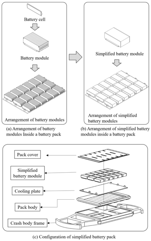
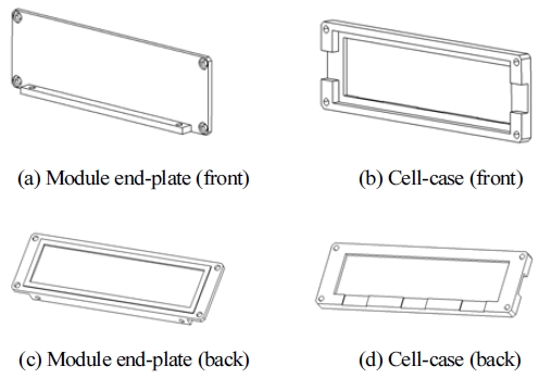
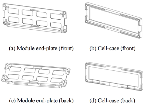
Fig. 1(a)은 파우치형 배터리 셀을 여러 층으로 적층할 수 있는 배터리 모듈과 이러한 모듈을 포함한 배터리 팩의 내부 구성을 나타내고 있다. 길이 360 mm, 높이 100 mm의 파우치 셀을 보호하는 배터리 모듈은 엔드-플레이트(End-plate)와 셀-케이스(Cell-case) 등으로 구성되어 총 18개 배터리 모듈이 6행 3열의 형태로 배터리 팩에 배치되었다.
배터리 팩 모델을 대상으로 최적 설계를 위한 유한요소해석을 수행할 경우, 배터리 팩을 구성하는 모든 부품의 요소(Element) 개수 및 접촉(Contact) 조건에 따라 상당히 긴 해석 시간이 필요하다. 또한, 다양한 케이스의 해석 결과가 필요한 최적 설계를 위해 반복적인 해석을 수행할 경우 수십 배 더 많은 시간이 소요될 수 있다. 따라서, 질량 및 가속도 효과가 지배적인 충돌 해석을 사용하여 배터리 모듈의 구조를 설계할 경우, 초기 해석 단계에서는 Fig. 1(a)과 같이 배터리 셀을 포함한 세부 구조가 전부 모델링된 배터리 모듈을 대신하여 배터리 셀 및 셀-케이스를 동일한 질량을 가진 단순화된 플라스틱 블록으로 구성하였다.22) 모델의 형상적인 차이가 발생할 수 있지만, 배터리 셀에 작용하는 응력을 감소시킨다는 경향성을 파악하기 위해 Fig. 1(b)와 같은 단순화된 배터리 모듈을 대상으로 충돌 해석을 진행하였다. 본 논문에서 제시하는 최적 설계 프로세스의 최종 단계에서 초기 모듈 모델과 최적화 모듈 모델의 성능 비교 검증을 위한 충돌 해석을 수행하였다.
Fig. 1(c)는 분해도를 통해 배터리 팩의 주요 구성 부품들을 나타내고 있다. 배터리 팩은 팩 커버, 팩 바디, 냉각 플레이트로 구성되도록 설계되었고, 이러한 배터리 팩은 바디 온 프레임(Body on frame) 및 스케이트보드 플랫폼(Skateboard platform)을 참고하여 설계된 프레임 구조물에 장착된다.23,24)
해석 진행을 위해서는 배터리 팩을 구성하는 부품의 물성(Material) 정보를 정의해야 한다. 차체와 배터리 팩 바디, 엔드-플레이트는 차량용 고강도강(High strength steel) SPFH 590으로 가정하였다.25-31) 팩 커버와 냉각 플레이트는 AL 6061로 가정하였으며, 모듈 셀-케이스는 PA6(Polyamide 6) 소재 물성을 기준으로 Table 1과 같이 각 부품의 물성을 정의하였다.32-34)
2.2 최적 설계를 위한 전방 및 기둥 측면 충돌 시험 조건
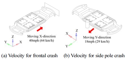
미국 고속도로 안전 보험 기관(IIHS: Insurance Institute for Highway Safety)에서 주관하는 차량 전방 충돌 시험의 경우, 40 mph(64 km/h)의 빠른 충돌 속도 조건에서 관성에 의한 부품의 파손, 이탈, 변형 등을 확인하여 충돌에 대한 부품의 안전 성능을 평가한다.35,36) 신차 평가 프로그램(NCAP: New Car Assessment Program)에서 주관하는 기둥 측면 충돌 시험의 경우, 전방 충돌에 비해 느린 18 mph(29 km/h) 속도로 충돌이 이루어지지만, 충돌에너지를 흡수해 줄 수 있는 측면 크럼플 존(Side crumple zone)의 크기가 차량의 전방 크럼플 존에 비해 비교적 작기 때문에 배터리 팩의 직접적인 변형 발생으로 인한 모듈 파손을 평가할 수 있다.37-39) 이러한 두 가지 시험 조건의 충돌 해석을 기반으로 배터리 모듈 및 팩의 최적 설계를 진행하였다.
3. 배터리 모듈 및 팩 최적 설계
3.1 초기 모델 분석 및 최적화 프로세스
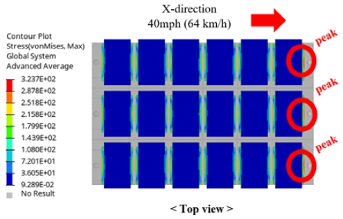
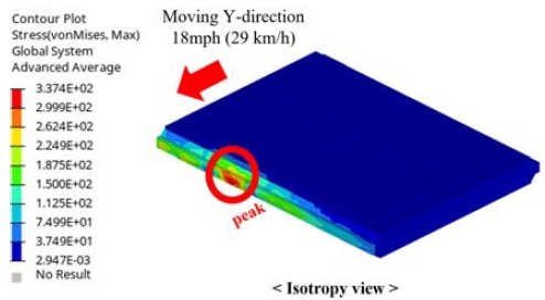
배터리 팩이 장착된 프레임 구조물의 전방 충돌 해석의 경우 40 mph(64 km/h)의 빠른 충돌 속도로 인하여 Fig. 3과 같이 최전방에 위치한 모듈에서 관성에 의한 최대 응력이 특징적으로 나타났다. 기둥 측면 충돌 해석의 경우 18 mph(29 km/h)의 속도로서 전방 충돌에 비해 느리기 때문에 배터리 모듈의 응력 결과에서 뚜렷한 특징이 나타나지 않았지만, Fig. 4와 같이 배터리 팩의 변형으로 인해 배터리 모듈과 팩 사이에 접촉이 발생할 가능성이 있었다. 이러한 경향성을 고려하여 전방 충돌 해석은 배터리 모듈의 설계에 주로 활용하였고 기둥 측면 충돌 해석은 배터리 팩 설계에 주로 활용하였다.
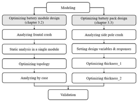
이러한 초기 모델 해석 결과를 바탕으로 배터리 모듈의 응력 및 변형 거동을 분석하여 전방 및 기둥 측면 충돌 조건에서 배터리 팩의 안전성과 경량화를 동시에 만족시키는 최적 설계를 진행하고자 Fig. 5와 같은 프로세스를 구상하였다.
작용 하중 분석을 통해 제약조건을 만족하는 범위 내에서 영향이 적은 형상 밀도 부위를 제거하는 위상 최적화 방법을 사용하여 배터리 모듈의 엔드-플레이트와 셀-케이스의 경량화를 진행하고자 하였다. 배터리 팩의 경량화를 위해서는 팩 커버, 팩 바디, 냉각 플레이트 총 3개 부품의 두께를 설계 변수로 지정하였다.40) 반응표면법(RSM: Response Surface Method)에 기반하여 다수의 설계 변수에 따른 반응 데이터를 전역적으로 취득하고 수많은 반응 값으로 구성된 반응표면 모델의 공간을 균형적으로 구성할 수 있는 GRSM(Global Response Search Method)을 적용하여 배터리 팩의 최적화를 진행하였다.41,42)
3.2 전방 충돌 조건에서의 배터리 모듈 형상 최적 설계
전체 어셈블리에 대한 해석을 진행할 경우, 요소 개수 및 접촉 조건에 따라 단일 모듈 단위의 정적 구조 해석(Static structural analysis)에 비해 긴 해석 시간이 요구된다. 초기 개발 단계에서 소요되는 시간 비용을 줄이기 위해 어셈블리 단위의 전방 충돌 해석 결과를 단일 모듈 단위의 정적 구조 해석 조건으로 재현하고자 하였다. 해석 대상 부품의 범위를 최소화하여 반복적인 케이스 스터디 과정에서 소요되는 시간을 단축하여 초기 개발 단계에서의 시간 비용을 줄이고자 하였다.43-45)
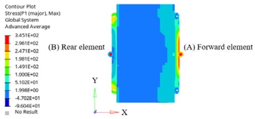
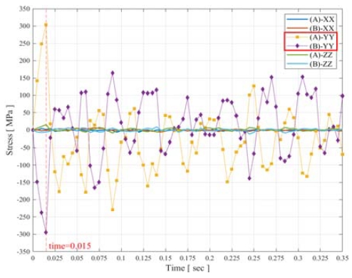
우선 Fig. 3과 같은 전방 충돌 해석과 유사한 결과를 가질 수 있도록 정적 구조 해석 조건에서의 등가 정적 하중(Equivalent static load)을 찾기 위한 분석을 진행하였다. 차체의 전방과 벽면의 접촉이 발생한 약 0.015초 뒤, 최전방에 위치한 배터리 모듈의 엔드-플레이트 중간 지점에서 최대 응력이 발생하였다. 배터리 팩에서 최전방에 배치된 모듈을 대상으로 최대 주응력(Max principal stress)을 확인한 결과, Fig. 6의 모듈 전방 요소(Forward element) (A)에서 인장, 모듈 후방 요소(Rear element) (B)에서 압축이 작용하였다.
배터리 모듈에 작용하는 충돌의 영향을 분석하기 위해 XYZ의 3축 방향 응력을 Fig. 7과 같이 비교하였다. Y축 방향 응력을 보면 Fig. 7(A)-YY와 같이 모듈 전방 요소에서 최대 303.7 MPa의 인장 응력이, Fig. 7(B)-YY와 같이 모듈 후방 요소에서 최대 294.3 MPa의 압축 응력이 발생하였다. X축과 Z축 방향과 비교하면 Y축 방향에서 응력의 편차가 더 크게 나타나는 것을 확인하였다. 이와 같은 분석을 통해 전방 충돌 시험 조건에서 배터리 모듈의 굽힘 변형으로 인해 인장과 압축이 발생하는 것을 알 수 있다.
전방 충돌 해석에서 도출된 Y축 방향 최대 응력과 유사한 결과를 단일 모듈 단위의 정적 구조 해석에서 구현할 수 있는 등가 정적 하중을 탐색하였다. Fig. 7(A)-YY와 같은 모듈 전방 요소의 최대 인장 응력과 Fig. 7(B)-YY와 같은 모듈 후방 요소의 최대 압축 응력에 대해 응력-변형률 관계식 (1)를 적용하면 초기 예상 하중 Fy를 예측할 수 있다. 이와 같이 예측된 초기 하중을 계산하기 위한 모듈 전방 요소 (A)와 모듈 후방 요소 (B)의 Y축 방향 최대 변위 δy는 Fig. 8과 같다.
| (1) |
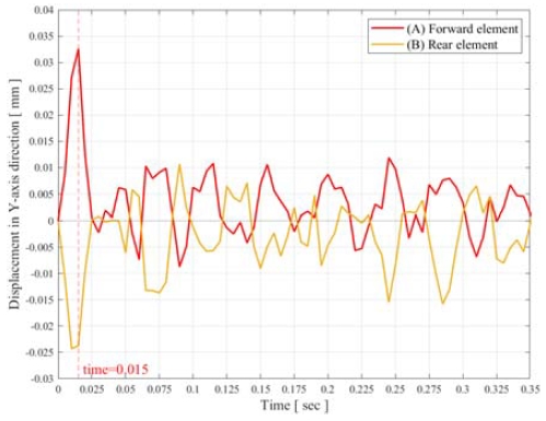
Comparison of displacements in the Y-axis direction between the forward element (A) and the rear element (B)
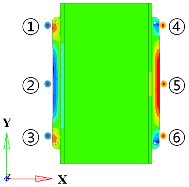
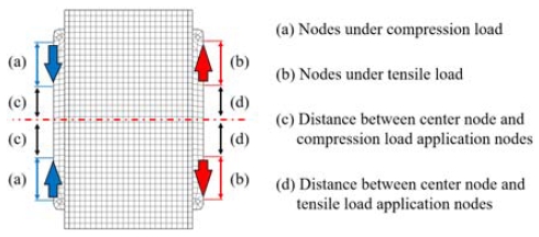
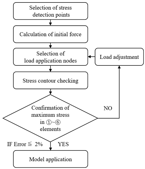
Fig. 6과 같이 Y축 방향으로 대칭적인 응력 컨투어를 참고하여 정적 구조 해석의 하중 조건을 설정하였다. 식 (1)을 통해 계산된 예상 하중 Fy의 초기값을 하중 적용 범위에 위치한 절점 개수로 나누어 분포 하중의 초기값으로 설정하였다. 설정된 분포 하중에 대해 정적 구조 해석을 수행하고, Fig. 9 ①~⑥ 위치에서 예측되는 응력을 기준으로 전방 충돌 해석과 정적 구조 해석의 결과를 비교하였다. 정적 구조 해석 결과에서 ①~⑥ 지점 요소의 Y축 응력을 확인하고, 해석 결과를 반영하여 압축 및 인장 하중이 적용되는 노드의 범위(Fig. 10(a) and (b))와 모듈 중심으로부터 하중 적용점까지의 거리(Fig. 10(c) and (d)), 예상 하중 Fy를 변화시켜가며 Fig. 11의 절차에 따라 해석 조건을 반복적으로 수정하였다. 그 결과 3가지 경우[(1) 엔드-플레이트 및 플라스틱 블록으로 단순화된 모듈 모델의 전방 충돌 해석 결과(Simplified module design under dynamic analysis conditions), (2) 엔드-플레이트 및 플라스틱 블록으로 단순화된 모듈 모델의 정적 구조 해석 결과(Simplified module design under static analysis conditions), (3) 엔드-플레이트, 셀-케이스, 셀을 고려한 상세 모듈 모델의 정적 구조 해석 결과(Detailed module design under static analysis conditions)]에 대한 ①~⑥ 위치의 최대 응력과 오차를 Table 2와 같이 확인하였다.
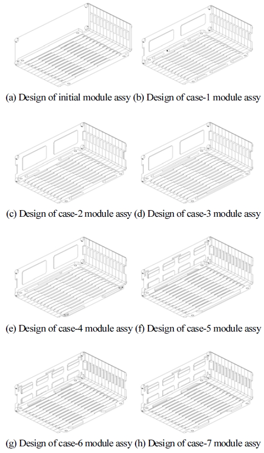
차량용 고강도강을 사용하여 설계된 엔드-플레이트의 질량은 배터리 모듈에서 비교적 높은 비중을 차지한다. 배터리 모듈의 경량화 설계를 위해 Fig. 12(a), (c)와 같은 초기 형상의 엔드-플레이트에 대해 위상 최적화를 수행한 결과 Fig. 13(b)와 같은 형상이 도출되었다. 다만, 단일 모듈 단위의 정적 구조 해석에서 초기 설계 프로세스의 효율화를 위해 Y축 방향 응력만을 고려한 위상 최적화를 수행하였다. 따라서 굽힘 등 Y축 이외의 방향의 변형이나 하중이 발생할 경우 위상 최적화로 얻어진 엔드-플레이트에는 예상보다 과도한 변형 또는 파손이 발생할 수 있다. 이점을 고려하여 구조 안전성을 향상시킬 수 있도록 엔드-플레이트의 중심부에 리브(Rib)를 추가하는 보강 설계를 진행하였다. 배터리 모듈의 조립에 필요한 서포트(Support) 및 나사(Bolt) 체결 부위를 제외한 나머지 부위에 대해 요소별 형상 밀도를 변화시키는 위상 최적화를 총 7개 케이스에 대해 추가로 진행하였고 그 결과는 Table 3과 같다.
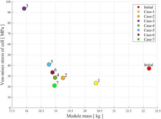
초기 모듈 설계와 위상 최적화를 통해 얻어진 7개 케이스에 대응하는 모듈 설계 형상들을 Fig. 14에 나타내었다. Fig. 14(a) 초기 모듈 설계와 비교하여 대부분의 케이스에서 배터리 셀에 작용하는 응력은 감소하였으며, 단일 모듈의 무게는 약 2~3 kg 경량화되었다. 배터리 셀의 응력과 모듈의 질량, 엔드-플레이트의 응력을 기준으로 최적의 특성을 갖는 Fig. 14(h) Case-7 모듈을 Fig. 15에 분해하여 부품을 나타내었다. Table 3에 나타낸 (h) Case-7 모듈 설계의 정적 구조 해석 결과를 보면, 배터리 셀에 발생하는 폰-미세스(Von-Mises) 응력은 37.2 MPa에서 21.0 MPa로 44 % 감소하였고, 단일 모듈의 질량은 22.2 kg에서 19.0 kg으로 14.6 % 감소하였다. 또한, 엔드-플레이트의 최대 응력이 SPFH 590 소재의 항복응력 420 MPa보다 낮은 것을 확인할 수 있다.29) 7개 케이스에 대한 정적 구조 해석을 통해 예측되는 질량과 폰-미세스 응력의 결과를 Fig. 16과 같이 산점도(Scatter plot) 형태로 표시하면 이를 통해 각 케이스의 설계 적합성을 비교 평가할 수 있다.
3.3 기둥 측면 충돌 조건에서의 배터리 팩 두께 최적 설계
기둥 측면 충돌 조건에서 배터리 팩의 최적 설계를 수행하였다. 먼저 배터리 팩의 초기 설계 모델에 대한 충돌 해석을 수행하였고 그 결과에 대한 분석을 바탕으로 18 mph(29 km/h)의 속도에서 배터리 모듈과 배터리 팩 사이의 간섭이 발생하지 않도록 팩 바디의 측면에 보강대를 추가하였다. 이와 같이 보강대가 추가된 배터리 팩 모델에 대해 기둥 측면 충돌 해석을 수행하였고 그 결과는 Fig. 17과 같다.
보강대를 추가하여 수정한 배터리 팩 설계 모델에 대해 배터리 팩의 구조적 강성 확보와 경량화를 목표로 GRSM 기반 최적화를 진행하였다.
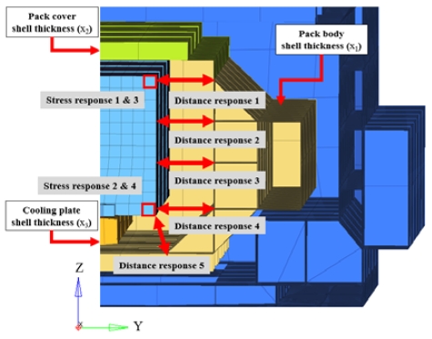
Table 4에 나타낸 것과 같이 팩 바디, 팩 커버, 냉각 플레이트 각각의 두께를 최적 설계 변수 x1, x2, x3로 지정하고 각각의 설계 범위를 가정하였다. 5개의 거리 반응 값(Distance response)과 4개의 요소 응력 반응 값(Element stress response)을 Fig. 18과 같이 정의하였다. 배터리 모듈과 팩 사이의 초기 거리 50 mm의 20 %인 10 mm를 최소 안전 거리로 제한하고, 요소 응력 반응 값에서 응력이 발생하지 않아야 한다는 제약 조건(Constraint)을 가정하였다. 제약 조건 범위 안에서 반응 값의 유/무를 확인하여 각 해석 케이스의 적합(Feasible) 및 부적합(Violated) 여부를 판단하였다. 모든 반응 값이 제약 조건을 만족하는 경우 중에서 가장 가벼운 경우를 최적 설계 결과로 얻을 수 있도록 무게를 표현하는 최적화 목적 함수를 정의할 필요가 있다. 부품의 무게는 부품의 두께에 비례하므로, 부품의 형상 설계 데이터를 토대로 부품 무게에 대한 두께 설계 변수 x1, x2, x3 각각의 기여도를 나타내는 비례상수 a1, a2, a3를 정량적으로 구하였다. 이 때 부품 무게를 정의하는 목적함수 f(x1, x2, x3)는 다음 식 (2)와 같이 쓸 수 있다.
| (2) |
본 연구에서는 배터리 모듈의 단순화를 통해 단위 모듈당 해석 시간과 비용을 크게 단축할 수 있다고 판단하여 완전요인배치법(Full factorial design) 기반의 실험계획을 적용하였다. 먼저, 1차 최적화를 위해 Table 4와 같은 설계 변수와 범위로 지정된 팩 바디, 팩 커버, 냉각 플레이트의 두께들을 대상으로 Table 5에 나타낸 것과 같이 3 수준의 완전요인배치법을 적용하여 총 27가지 케이스의 기둥 측면 충돌 해석을 수행하였다. 1차 최적화 결과 팩 바디의 두께는 10 mm, 팩 커버의 두께는 5 mm, 냉각 플레이트의 두께는 2 mm인 Case-4가 모든 제약조건을 만족하면서 27개의 케이스 중 1.088 ton의 가장 가벼운 질량을 제공하였다.
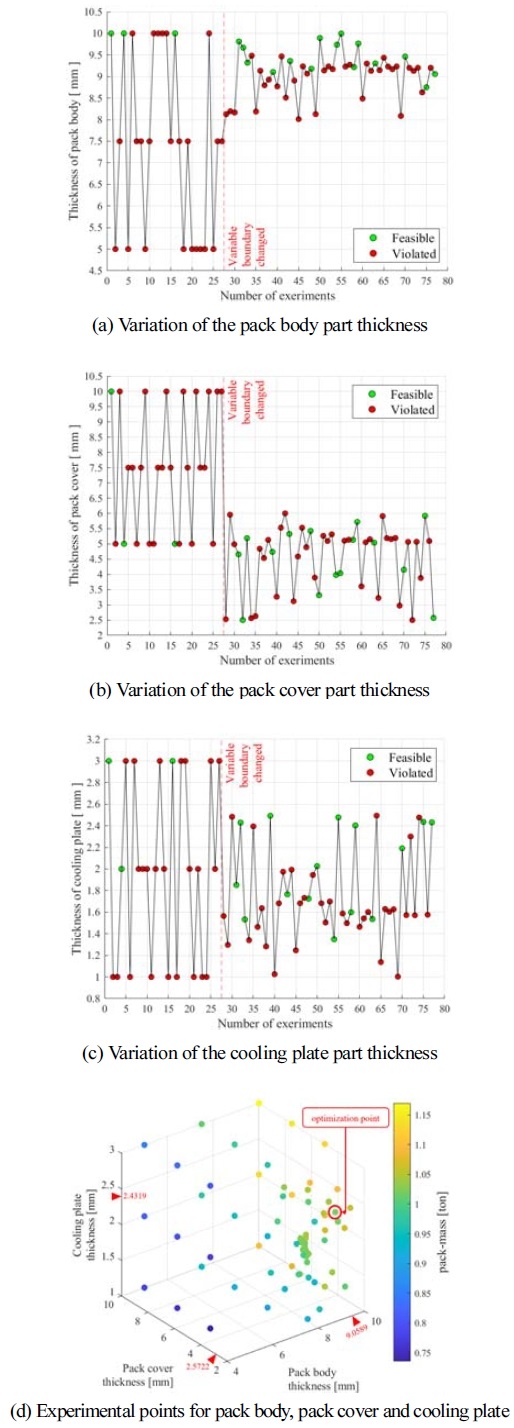
1차 최적화 결과를 토대로 하는 2차 최적화에서는 설계 변수의 Upper 및 Lower 범위를 Table 4의 경우보다 좁은 범위로 수정하였다. 2차 최적화에서는 전역 반응 값을 취득하기 위해 변수의 형식을 연속 형식 (Continuous type)으로 설정하였다. 1차 최적화보다 작은 범위 내에서 유전알고리즘에 의해 최적점을 찾아갈 수 있도록 설정하였고, 총 50번의 추가적인 해석 케이스를 Table 6과 같이 수행하였다. GRSM 방식을 통한 2차 최적화의 결과를 Table 7에 나타내었다.
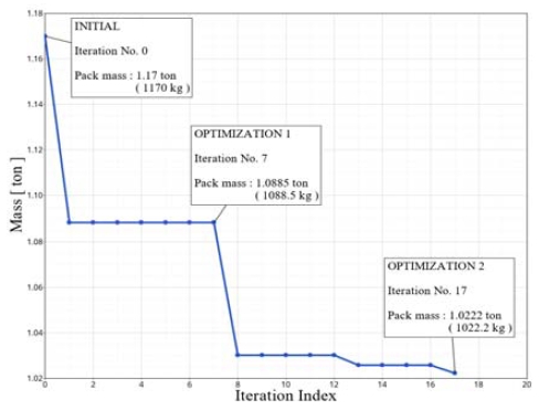
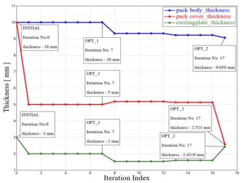
그 결과, 팩 바디의 두께는 9.06 mm, 팩 커버의 두께는 2.57 mm, 냉각 플레이트의 두께는 2.43 mm인 Case-77이 기둥 측면 충돌 조건의 제약 조건을 만족하면서 1.022 ton의 질량을 제공하여 초기 Case-1 모델의 질량 1.17 ton에 비해 12.65 % 경량화 가능함을 알 수 있다. 설계 반복 횟수에 따른 질량과 두께의 변화 추세를 Fig. 19와 Fig. 20, Fig. 21에 각각 나타내었다.
3.4 배터리 모듈 및 팩 최적 설계 결과 및 평가
3.2에서 전방 충돌 시험 조건에 대해 도출된 Case-7의 모듈 설계와 3.3에서 기둥 측면 충돌 시험 조건에 대해 도출된 Case-77의 팩 설계를 종합하였고, 이 모델에 대해 전방 및 기둥 측면 충돌 해석을 진행하였다.
Case-7의 모듈과 Case-77의 팩을 종합한 설계 모델에 대해 전방 충돌 시험 조건의 해석을 수행한 결과, Fig. 22에 나타낸 것과 같이 배터리 셀에 작용하는 폰-미세스 응력은 최대 62.3 MPa로서 초기 모듈과 Case-1의 팩을 적용한 모델의 해석 결과인 215.4 MPa에 비해 71 % 감소하였다. 또한, 기둥 측면 충돌 시험 조건의 해석을 수행한 결과, Fig. 23에 나타낸 것과 같이 Case-7의 모듈과 Case-77의 팩을 종합한 설계 모델에서 배터리 모듈과 배터리 팩 사이의 접촉이 발생하지 않았다.
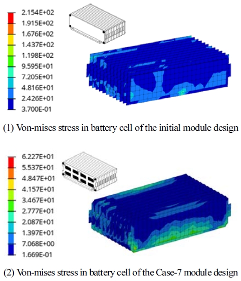
Comparison of von-mises stress between the initial module & initial pack design and Case-7 module & Case-77 pack design
전방 및 기둥 측면 충돌 시험 조건의 해석을 통해 초기 모델과 최적화 모델 각각에 대해 예측되는 배터리 팩 질량과 셀에 발생하는 최대 응력을 비교하여 Table 8에 나타내었다. Case-7의 모듈과 Case-77의 팩 설계를 적용한 최적화 모델의 질량이 1.04 ton으로서 초기 모듈과 Case-1의 팩 설계를 적용한 초기 모델의 질량인 1.23 ton에 비해 약 15.8 % 경량화 가능하였다.

Comparison of the mass of the pack and the maximum stress in the cell between the initial and optimal designs
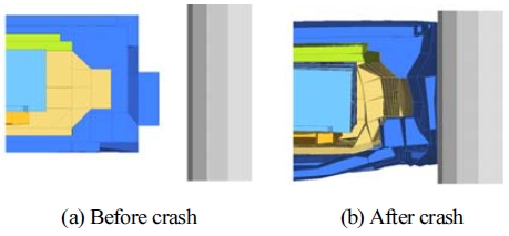
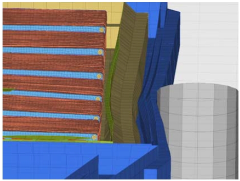
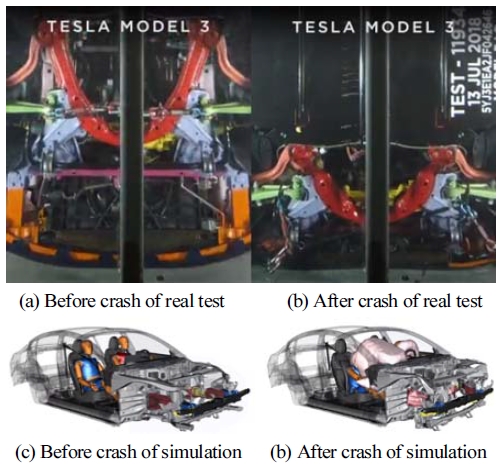
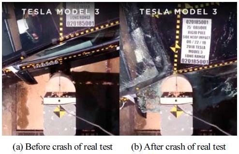
본 논문에서 얻은 해석 결과의 타당성을 평가하기 위해 T사 차량 모델의 충돌 시험과 문헌을 참고하였다.46-48) 결과를 보면, 전방 충돌의 경우 Fig. 24와 같이 크럼플 존에서 충돌에 의한 변형이 대부분 발생하였으며, 배터리 팩에서는 충돌에 의한 직접적인 변형이 크게 발생하지 않은 것을 확인할 수 있다. 다만, 관성 효과로 인해 배터리 팩 부품의 변형 또는 이탈이 발생할 수 있을 것이다. 측면 기둥 충돌의 경우 Fig. 25와 같이 기둥의 침투(Intrusion)로 인한 차체의 변형량이 탑승자 및 배터리 팩까지 도달하지 않도록 해야 한다.
4. 결 론
본 연구에서는 전기 자동차의 배터리 팩 초기 개발 단계에서 배터리 모듈 및 팩의 구조 강성 확보를 통해 차량 충돌에 의한 배터리 셀의 손상을 감소시키면서도 배터리 팩의 경량화를 달성할 수 있는 최적 설계 프로세스를 제안하고자 하였다. 최적 설계를 위한 조건으로는 차량의 전방 충돌 및 기둥 측면 충돌 시험을 고려하였다. 본 논문에서 제안한 최적 설계 프로세스와 그에 따른 결과는 다음과 같다.
- 1) 40 mph(64 km/h) 속도의 차량 전방 충돌에 의해 배터리 모듈에 작용하는 응력과 변형률 거동을 분석하여 등가의 정적 하중을 정의하였다. 이를 통해 배터리 팩 단위의 해석 결과를 단일 모듈 단위의 정적 구조 해석으로 변환하여 최적 설계에 소요되는 해석 시간을 단축하였다.
- 2) 등가 정적 하중을 적용한 단일 모듈 단위의 해석에 위상 최적화를 적용한 재설계를 수행하여 모듈 엔드-플레이트 및 셀-케이스 부품의 경량화 최적 설계를 도출하였다.
- 3) 18 mph(29 km/h) 속도의 기둥 측면 충돌에서의 배터리 팩 변형을 분석하여 팩 바디, 팩 커버, 냉각 플레이트 총 3개 부품의 두께를 설계 변수로 정의하고 GRSM 알고리즘을 활용한 최적화를 수행하였다. 배터리 팩과 모듈 사이의 접촉을 방지하는 77개의 케이스 중에서 제약조건을 만족하면서 가장 경량화된 배터리 팩 모델을 도출하였다.
- 4) 전방 충돌과 기둥 측면 충돌 시험 조건을 통해 도출된 배터리 모듈과 팩 모델을 종합한 최적 설계 모델에 대해 해석 검증을 진행한 결과, 배터리 셀에 발생하는 최대 폰-미세스 응력은 215.4 MPa에서 62.3 MPa로 71.1 % 감소하였으며, 배터리 팩의 질량은 1.233 ton에서 1.039 ton으로 15.7 % 경량화 되었다.
- 5) 다만, 본 연구에서는 단순화 설계된 차량 프레임 구조물에 배터리 팩을 적용하여 충돌 해석을 수행하였고 이는 전체 차량 모델을 그대로 사용한 충돌 해석에 비해 실제 차량 거동 예측의 정확도는 낮을 수 있다. 그러나, 전체 차량 모델의 세부 구조가 결정되지 않은 차량 개발 초기 단계에서는 단순화 모델 기반의 빠른 해석을 통해 신속한 초기 설계 안을 우선 도출하는 것이 도움이 될 수 있다.
이러한 최적 설계 프로세스는 차량의 후방 충돌 및 하부 충돌과 같은 다른 충돌 시험 조건에서도 유사한 방식으로 수행될 수 있으며, 향후 가볍고 안전한 전기 자동차 배터리 팩 개발에 소요되는 시간과 비용의 단축에 활용될 수 있을 것이다.
Nomenclature
| Fy : | force in Y-axis direction (N) |
| σyy : | stress component in the Y-axis direction on a plane perpendicular to the Y-axis (MPa) |
| E : | young’s modulus (MPa) |
| δy : | y-axis direction displacement (mm) |
| lx : | x-axis direction length of element (mm) |
| ly : | y-axis direction length of element (mm) |
| lz : | z-axis direction length of element (mm) |
| x1 : | design variable for pack body thickness |
| x2 : | design variable for pack cover thickness |
| x3 : | design variable for cooling plate thickness |
| a1 : | coefficient of calculation pack body mass |
| a2 : | coefficient of calculation pack cover mass |
| a3 : | coefficient of calculation cooling plate mass |
Acknowledgments
본 연구는 2024 년도 정부(교육부) 및 정부(산업통상자원부)의 재원으로 한국연구재단의 4단계 BK21 사업(5199990814084)지원과 한국산업기술진흥원의 산업혁신인재성장지원사업(P0020536, 2024년 산업혁신인재성장지원사업) 및 2022년도 한국산업기술평가관리원(No.20022377, 고열전도성 열계면 소재 적용 전기차 배터리 팩 시스템 냉각 성능 향상 기술 개발,141587318)의 지원을 받아 수행한 연구입니다.
References
- S. H. Kim, “EU Carbon Regulation and Evaluation of Decarbonization Technology Regulation,” Technology Policy Mechanical Engineering, Vol.1, No.2, pp.3-23, 2022.
- S. W. Cho, “Understanding and the Reasons for ESG Management,” Food Industry and Nutrition, Vol.26, No.2, pp.1-4, 2021.
- W. Y. Ki, “Development Trend of Battery Safety for Electric Vehicles,” The Korean Society of Automotive Engineers, p.1664, 2022.
-
T. Kisters, J. Kuder, R. Langkemper, S. Nau and S. Schopferer, “Strain-Rate Dependence of the Failure Behavior of Lithium-Ion Pouch Cells under Impact Loading,” Journal of Energy Storage, Vol.41, Paper No.102901, 2021.
[https://doi.org/10.1016/j.est.2021.102901]

-
G. P. Lim and M. S. Kim, “Demonstration Study About Fire Detecting, Protecting and Extinguishing Method of ESS Lithium-Ion Battery,” Journal of the Korea Academia-Industrial Cooperation Society, Vol.24, No.6, pp.556-563, 2023.
[https://doi.org/10.5762/KAIS.2023.24.6.556]

- S. H. Lee, “A Study on the Cooling and Impact Performance of an EV Battery Pack Case by FEM Analysis,” M. S. Thesis, Chosun University Graduate School, 2023.
- J. H. Cho, D. H. Gang, S. H. Cho and H. K. Kim, “Optimum Design of Integrated Battery Pack Using Structural and Flow Analysis,” The Korean Society of Automotive Engineers, p.821, 2021.
- G. S. Lee, H. H. Choi, S. Y. Lee, W. B. Song, B. M. Kim, Y. H. Choi and B. D. Youn, “Reliability Based Optimal Design of Electric Vehicle Battery Modules Considering Battery Swelling,” The Korean Reliability Society, p.35, 2023.
-
P. Chen, Y. Xia, Q. Zhou and S. Liu, “Staggered Layout of Battery Cells for Mitigating Damage in Side Pole Collisions of Electric Vehicles,” eTransportation, Vol.16, Paper No.100238, 2023.
[https://doi.org/10.1016/j.etran.2023.100238]

-
Y. Cui, J. Liu, X. Han, S. Sun and B. Cong, “Full-Scale Experimental Study on Suppressing Lithium-Ion Battery Pack Fires from Electric Vehicles,” Fire Safety Journal, Vol.129, Paper No.103562, 2022.
[https://doi.org/10.1016/j.firesaf.2022.103562]

-
C. Zhang, S. Santhanagopalan, M. A. Sprague and A. A. Pesaran, “A Representative-Sandwich Model for Simultaneously Coupled Mechanical-Electrical-Thermal Simulation of a Lithium-Ion Cell under Quasi-Static Indentation Tests,” Journal of Power Sources, Vol.298, pp.309-321, 2015.
[https://doi.org/10.1016/j.jpowsour.2015.08.049]

-
Z. Zou, F. Xu, H. Tian and X. Niu, “Testing and Impact Modeling of Lithium-Ion Prismatic Battery under Quasi-Static and Dynamic Mechanical Abuse,” Journal of Energy Storage, Vol.68, Paper No.107639, 2023.
[https://doi.org/10.1016/j.est.2023.107639]

- Y. Leost, “Crash Simulations of Electric Cars in the EVERSAFE Project,” Conference LS-DYNA Forum 2014, 2014.
-
J. B. Bae and J. J. Kim, “Structural Safety Analysis of Battery Housing for Electric Vehicles According to the Horizontal Cross-Member Structure,” Journal of the Korean Society of Manufacturing Process Engineers, Vol.22, No.3, pp.92-99, 2023.
[https://doi.org/10.14775/ksmpe.2023.22.03.092]

- K. H. Choi, S. H. Lee, H. B. Choi, G. Y. Go, J. H. Song and J. Y. Kim, “The Study on Battery Pack Case of Electric Vehicle Using Collision Analysis,” The Korean Society of Manufacturing Process Engineers, p.222, 2021.
- H. J. Kim, B. I. Seo and C. Kim, “Design Optimization of New Honeycomb Battery Structures for Maximum Crash Energy Absorption and Effective Mechanical Properties,” The Korean Society of Automotive Engineers, p.1309, 2022.
- S. D. Kim, H. S. L. M. Kwark, C. M. Choi and C. M. Shin, “A Study on Impact Analysis of Battery Pack Case With Thermoplastic Fabric Composite Material,” The Korean Society of Automotive Engineers, p.818, 2022.
- K. H. Choi, H. B. Choi, S. H. Lee, G. Y. Go, J. H. Song and J. Y. Kim, “A Study on the Side Impact Analysis of Electric Vehicle Battery Pack Case,” The Korean Society of Automotive Engineers, pp.72-73, 2021.
- R. Arbelaez, “As Heavy EVs Proliferate, Their Weight May Be a Drag on Safety,” IIHS-HLDI, https://www.iihs.org/news/detail/as-heavy-evs-proliferate-their-weight-may-be-a-drag-on-safety, , 2023.
-
M. H. Jeong, Y. I. Kim and G. J. Park, “Nonlinear Dynamic Response Structural Optimization for the Structure Integrating the Body-In-White and Battery Pack of an Electric Vehicle Considering a Side Pole Impact Test,” Transaction of the Korean Society of Automotive Engineers, Vol.29, No.7, pp.683-691, 2021.
[https://doi.org/10.7467/KSAE.2021.29.7.683]

-
F. Zhu, X. Du, J. Lei, L. Audisio and D. Sypeck, “Experimental Study on the Crushing Behaviour of Lithium-Ion Battery Modules,” International Journal of Crashworthiness, Vol.26, No.6, pp.598-607, 2021.
[https://doi.org/10.1080/13588265.2020.1766397]

- K. H. Park, H. S. Kim, K. H. Choi and H. J. Kim, “A Study on the Strength of Honeycomb and Structure Reinforced by Cylindrical Reinforcement at Equivalent Mass,” The Korean Society of Mechanical Engineers, pp.503-506, 2003.
- Hyundai Group, “5 Key Benefits of a Dedicated E-GMP Platform for Electric Vehicles,” https://www.hyundai.co.kr/story/CONT0000000000089036, , 2024.
- J. H. Kim, W. J. Jang and D. Y. Kim, “Analytical Study on EV Frame Body Validation and Performance Improvement,” The Korean Society of Automotive Engineers, pp.72-80, 2021.
-
S. Liu, Z.-Q. Tong, Z.-L. Tang and Z.-H. Zhang, “Design Optimization of the S-Frame to Improve Crashworthiness,” Acta Mechanica Sinica, Vol.30, pp.589-599, 2014.
[https://doi.org/10.1007/s10409-014-0032-y]

- WorldAutoSteel, AHSS Application Guidelines, “T ransformation Induced Plasticity(TRIP),” https://ahssinsights.org/metallurgy/steel-grades/3rdgen-ahss/transformation-induced-plasticity-trip/, , 2024.
-
F. Zhu, R. Zhou and D. J. Sypeck, “Numerical Modeling and Safety Design for Lithium-Ion Vehicle Battery Modules Subject to Crush Loading,” Energies, Vol.14, Paper No.118, 2021.
[https://doi.org/10.3390/en14010118]

- Posco Newsroom, “#3 Simpler and Lighter, E Autopos’ Battery Pack,” https://newsroom.posco.com/en/e-autopos-unboxing-3-simpler-and-lighter-e-autopos-battery-pack/, , 2024.
- Posco Products, “High Strength Low Alloy Steel, 590C,” http://product.posco.com/homepage/product/eng/jsp/process/s91p2000110h.jsp, , 2024.
-
B. Xia, F. Liu, C. Xu, L. Yongzhi, W. Zheng and W. Wang, “Experimental and Simulation Modal Analysis of a Prismatic Battery Module,” Energies, Vol.13, Paper No.2046, 2020.
[https://doi.org/10.3390/en13082046]

- S. M. Choi, Y. G. Song, S. J. Park, S. Y. Park, Y. G. Song and H. Y. Gang, “Structural Vibration Analysis for End-Plate of Battery Pack Module System,” Proceedings of the KSMPE Conference, p.349, 2023.
- A. K. Hellier, P. P. Chaphalkar and G. B. Prusty, “Fracture Toughness Measurement for Aluminium 6061-T6 Using Notched Round Bars,” 9th Australasian Congress on Applied Mechanics (ACAM9), pp.27-29, 2017.
- D. I. Kim, S. W. Nam, J. H. Lee, J. Y. Kim and C. R. Park, “A Study of Impact Analysis for Battery Pack of Aluminum Sheet,” KSAE Spring Conference Proceedings, p.621, 2023.
- S. H. Yu, M. S. Kim, H. S. Yoon, J. S. Park, S. M. Jeon, and J. H. Sim, “A Study on the Mechanical Properties and Performance Prediction Simulation of PA6/GF Composite Materials with Injection Molding Pressure,” Textile Coloration and Finishing, Vol.34, No.1, pp.46-57, 2022.
-
E. R. Teoh and S. S. Monfort, “IIHS Small Overlap Frontal Crash Test Ratings and Real-World Driver Death Risk,” Traffic Injury Prevention, Vol.24, No.5, pp.409-413, 2023.
[https://doi.org/10.1080/15389588.2023.2199342]

- J. S. Byun, J. H. Kim, J. G. Park, J. S. Choi, T. O. Park and D. H. Kim, “Research on New FEM Structure for Electric Vehicle Platform,” KSAE Spring Conference Proceedings, pp.583-589, 2023.
- BID, Bloomberg Philanthropies, FIA Foundation, Global NCAP, ICRT, Side Pole Impact Test, https://www.latinncap.com/en/our-tests/adult-occupant/side-pole-impact-test, , 2023.
- J. K. Min, D. H. Sim and H. J. Choi, “A Study of Occupant Injury Reduction for Euro NCAP Side-Pole Test,” KSAE Annual Conference Proceedings, pp.2201-2210, 2010.
- S. B. Jang, Y. S. Lee, C. M. Shin, G. C. Kim and W. S. Ji, “Side Impact Analysis for Plastic Battery Pack Case of Electric Vehicles,” The Korean Society of Automotive Engineers, pp.715-716, 2021.
-
R. Li, Y. Pan, X. Zhang, W. Dai, B. Liu and J. Li, “Mechanical Safety Prediction of a Battery-Pack System under Low Speed Frontal Impact via Machine Learning,” Engineering Analysis with Boundary Elements, Vol.160, pp.65-75, 2024.
[https://doi.org/10.1016/j.enganabound.2023.12.031]

- Altaire, “Global Response Search Method(GRSM),” https://help.altair.com/hwdesktop/hst/topics/design_exploration/method_global_response_surface_method_r.htm?zoom_highlight=Global+Response+Search+Method+GRSM, , 2024.
- K. W. Joo, K. M. Jang and K. S. Kim, “Study on Optimization of Li-Ion Battery Pack Design by RSM,” The Korean Society of Semiconductor & Display Technology, Vol.14, No.1, pp.39-43, 2015.
-
G. J. Park, “Technical Overview of the Equivalent Static Loads Method for Non-Linear Static Response Structural Optimization,” Struct Multidisc Optim, Vol.43, pp.319-337, 2011.
[https://doi.org/10.1007/s00158-010-0530-x]

- S. O. Park, Multi-Model Optimization Using the Equivalent Static Loads Method, Ph. D. Dissertation, Hanyang University, 2021.
-
H. A. Lee and G. J. Park, “Nonlinear Dynamic Response Topology Optimization Using the Equivalent Static Loads Method,” Computer Methods in Applied Mechanics and Engineering, Vol.283, pp.956-970, 2015.
[https://doi.org/10.1016/j.cma.2014.10.015]

- M. Schäffer, M. Münster, R. Sturm and H. E. Friedrich, “Development of an Optimised Side Crash Concept for the Battery-Electric Vehicle Concept Urban Modular Vehicle,” Conference 14. LS-DYNA Forum, 2016.
-
G. Sankaran and S. Venkatesan, “Standardization of Electric Vehicle Battery Pack Geometry Form Factors for Passenger Car Segments in India,” Journal of Power Sources, Vol.502, Paper No.230008, 2021.
[https://doi.org/10.1016/j.jpowsour.2021.230008]

- Tesla, The Tesla Team, “Model 3 Achieves the Lowest Probability of Injury of Any Vehicle Ever Tested by NHTSA,” https://www.tesla.com/de_de/blog/model-3-lowest-probability-injury-any-vehicle-ever-tested-nhtsa, , 2024.
