Development of a Coating Machine for Making Automotive Seat Covers
Copyright Ⓒ 2017 KSAE / 148-01
Abstract
Automotive seat covers with olefin film imported from foreign companies exhibit some problems such as low peeling strength and high burning rate. The traditional manufacturing process requires gas flame or direct heating for the laminating step. This paper introduces an alternative solution that replaces the olefin film and flame lamination method in making automotive seat covers or interior fabrics. We adopt a new manufacturing concept that applies a water-based resin coating to develop a coating system. The coating machine was successfully developed and tested. Results are intended to contribute to improving the quality and productivity of automotive seat cover production.
Keywords:
Gravure coating, Machine development, Coating machine, Design and analysis, Automotive seat covers1. Introduction
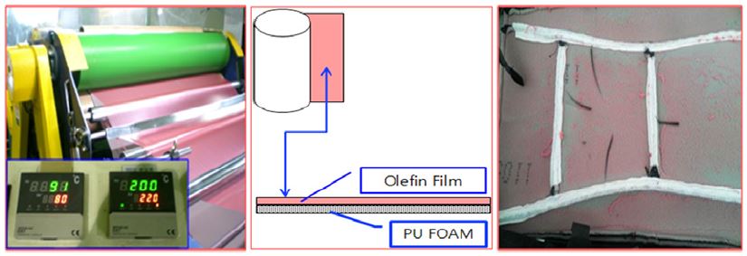
Traditionally, flame lamination has been widely used in automotive industry to make seat cover or interior fabrics1) (Fig. 1). This method can be used to adhere polyurethane foam into a textile material. A web of polyurethane(PU) foam or olefin film that melts when passed over a gas flame and combines with the fabrics material from a second roller. A thin molten layer is created on the surface, allowing substrates to bond to the foam when passed under a nip roller. However, the major disadvantage is the high capital cost of equipment, for instance, carbon filter absorbers are needed to clean up the gaseous emissions so that they comply with legislative requirements.2)
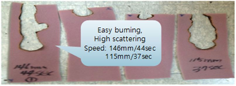
In addition, olefin films sheet depends on the importation from foreign companies. Moreover, the fabric and PU foam of the seat cover that is bonded by olefin film can be peeled or detached due to the rubbing of the driver or passenger after a certain time of usage(Fig. 2). This disadvantage makes a dissatisfaction of automotive customer. The experiment shows that the peeling or detachment occurs after 3,000 times of cycles using robot car MS-SPEC 2 peeling test. Olefin is also very heat sensitive. Although the flame retardant is added to the polyurethane sponge with 5 mm thickness, olefin film adhesive sponge also temporarily is unstable during flammability tests based on automotive standard MS-300-08(Fig. 3). The speed of burning propagation is up to 146 mm after 44 seconds. This is not safe for day-to-day use of vehicles.
Due to previously mentioned problems, the quality of the seat cover is not good as expectation. Therefore, it is necessary to find an alternative solution that replaces the olefin film and flame lamination method for making automotive seat covers or interior fabrics. Based on information and literature review, we found that there is no domestic patent on automotive seat fabric and production method using a water-based resin.3) The research projects to be carried out can be summarized as follows:
- Develop new method that applies a water-based resin coating(new manufacturing concept).
- Development of coating system equipment(new machine tool development for the new manufacturing process).
2. Manufacturing Concept
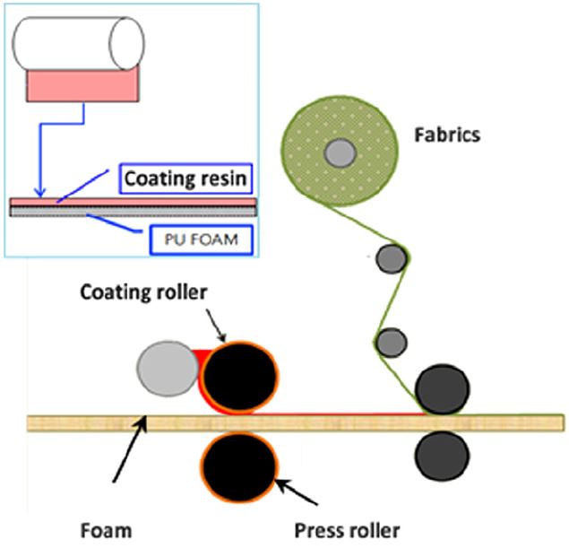
PU foam is firstly coated with liquid resin by rollers and then laminated with fabric materials by laminating process as shown in Fig. 4, Fig. 5 depicts a manufacturing line where the aqueous-based resin coating method is applied to make the final automotive seat cover products. It can be seen that the coating resin that resolves the disadvantages of olefin film as previously mentioned in the introduction section.
The requirements and process parameters include the speed of the rollers, gap between rollers, coating material, viscosity of resin material. Moreover, no flame or direct heating is involved in this process. The gap between coating rollers is important and should be maintained by manual or automatic way in order to coat variety of thicknesses of polyurethane foam sheet. Aqueous resin which is a plastic material will be applied for coating(the kind of resin is confidential). Uniform layer of coating material must be applied. Drying system will also be incorporated in this conceptual idea. The foam is coated first and then laminated with the fabric material to make final products. This is an adhesive-based lamination. PU foam sheet coated with adhesive by a coating process is bonded with another substrate(fabric). In this case, the coating process is the heart of the laminating process.4)
3. The Selection of Coating Method
Coating is a process in which one or several layers of material are deposited on the surface of a substrate. Many different coating techniques have been developed to address the characteristics of a wide range of coating materials and substrates.3) The idea of coating method in this work is originated from the textile industry. We focus on aqueous resin as the coating material. It functions as an adhesive substance.
Coating flow is fluid flow which results in a thin film of liquid forming onto a surface that needs to be coated. The terminology associated with coating methods is diverse but they can all be classified, according to Shim5) and Benkreira et al.6) into the following broad ways: free coating, metered coating, transfer coating, roll coating, and gravure or engraved roll coating, screen coating, and spay coating.
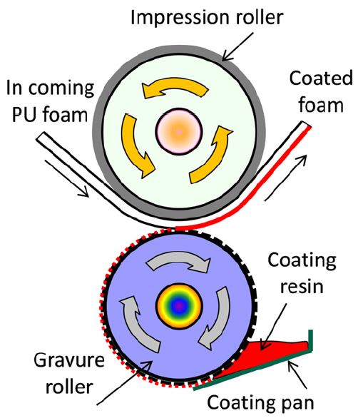
Gravure roll coating is a technique used to coat fluids of a wide range of viscosities onto substrates at high speeds.7,8) Gravure roll coating is the process where engraving on the roller acts as a metering device. The engraved roller is partly submerged in the coating bath and as it rotates, coating liquid fills the engraved pattern and excess coating liquid in the form of a film on the roller’s surface9) (Fig. 6). Coating thicknesses in the range of less than 1μm up to 50 μm can be achieved, making this a versatile process which fulfills the requirement of automotive seat cover products.
Although there are many coating methods, based on the equipment used, metering method, coating materials and substrate properties, we select gravure coating because this method can be applied to a wide range of level coating from medium to high viscosity. Moreover, a high precision and versatility can be achieved by this method as well as some advantages. such as precision control of coat weight, very low weight coat possible, and webs diversity.10)
4. Development of the Gravure Coating Machine
4.1 Development procedure and conceptual design
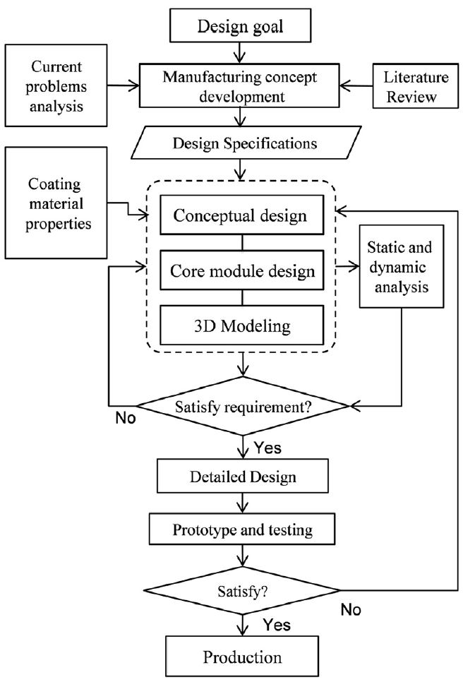
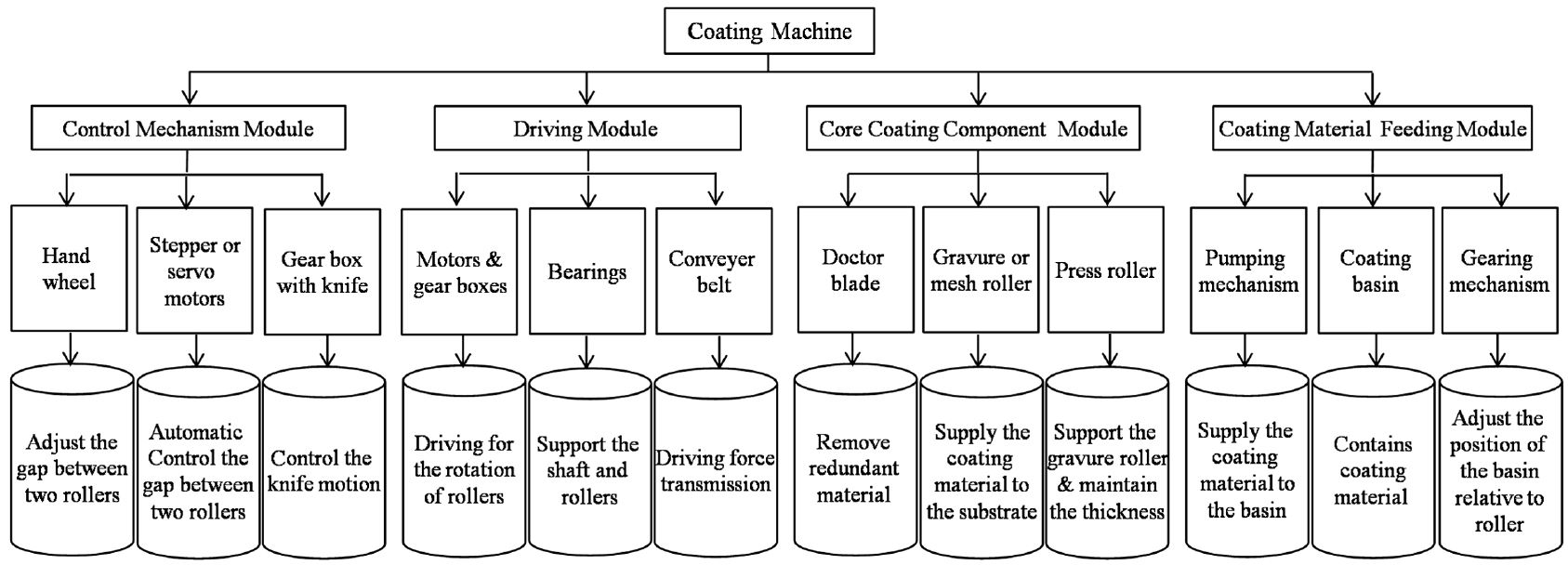
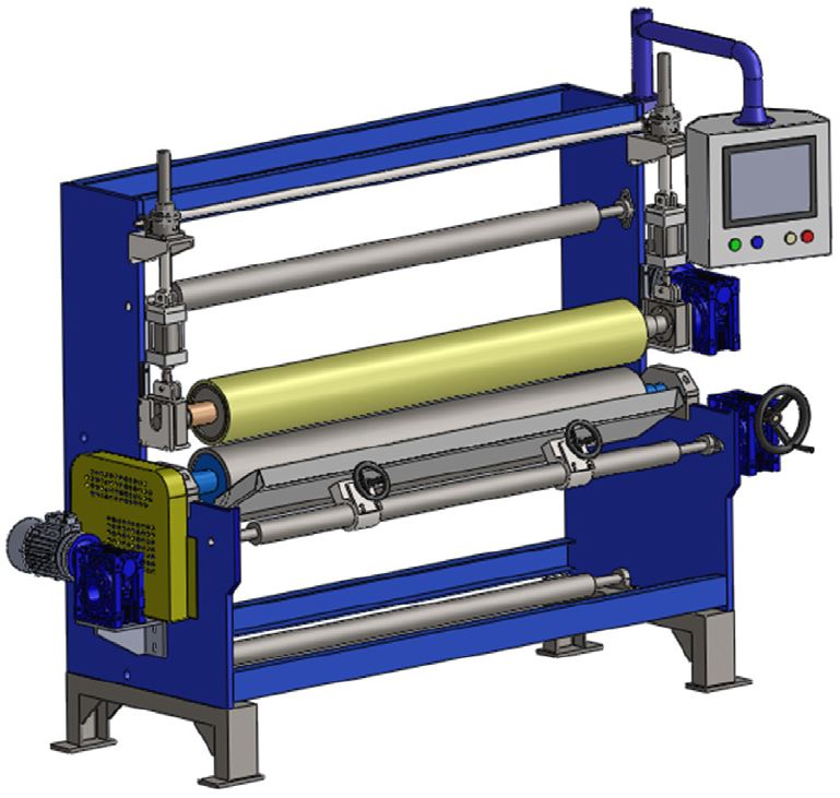
The systematic procedure of coating machine development is presented in Fig. 7. The main structure of the coater includes the four modules as shown in Figure 8. The four main modules are control mechanism module, driving module, core coating module, and coating material feeding module. The machine should be as simple as possible, but it must be modern and satisfies the functional requirements. The specifications of the coating machine are depicted in Table 1. The 3D model of the coating machine(Fig. 9) is generated using CAD software. This geometrical model is useful for static and dynamics analysis later.
4.2 Static and dynamic analysis
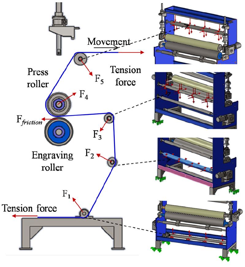
After performing initial design, the analysis using CAE tool was carried out to verify the static and dynamic characteristics. The diagram of external load is shown in Fig. 10. The loads acting on the components of the machine include the gravity force, tension force of the coated product and driving torque of the motors.
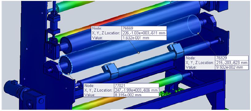
We consider the stress and deformation of the machine due to their effect on the machine performance. The maximum stress is 163 N/mm2. It can conclude that all the components are strong enough. Fig. 11 shows the deformation under maximum working load. The machine has small displacement.
For the dynamic analysis, we use the Solidworks simulation tool to solve modal and dynamic analysis problem in which five modes are considered. The modal results are shown in Table 2. The natural frequencies are higher than the operational frequencies of the coating machine. Therefore, there will be no resonant vibration in reality. It is no need to do harmonic analysis. The coating machine is safety in terms of dynamics.
4.3 Design the graved pattern of gravure roller
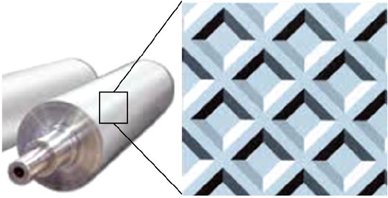
The most important components are the gravure roller and impression roller. The gravure roller is engraved with pattern. The choice of cell structure is dependent upon the coating viscosity and flow parameters. Square pyramid pattern was selected as shown in Fig. 12 because the required coating weight per square meter is low. To select the correct gravure pattern, we used the reference of coat weight chart. For a given coat weight, selection is based upon the solids content of the coating, its viscosity, and its flow characteristics. According to the required coating weight per square meter, the parameters the gravure pattern was determined based on the data of Anilox Roller. The parameter of designed gravure roller is shown in Table 3. The diameter and length of the engraved roller are 213 mm and 1800 mm, respectively.
5. Machine Construction and Testing Results
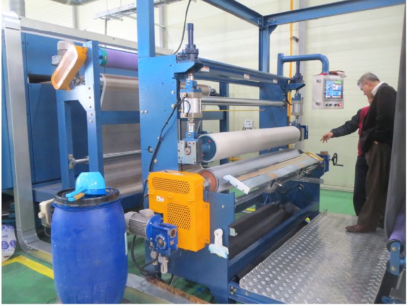
After detail design, the gravure roller coating machine was manufactured in order to verify the new coating process to make automotive seat cover(Fig. 13). The functionality of the coater was tested. The quality and productivity of coated product meets the requirements successfully.
The seat cover with resin-based coating endures up to 25,000 cycles of durability test without peeling compare to 3,000 times of olefin-based product. In addition, the coated product was also tested according to Hyundai MS-300-08 flame retardant test. The test results show that the species is determined to be noncombustible flame; combustion fumes directly from the lateral both less than 10 mm from the test sample over 8 times(Fig. 14).
6. Conclusions
It can be concluded that the coating machine was designed by scientific and systematic procedure. The static and dynamic analyses of the machine have been carried out in order to verify the mechanical behavior of the machine. The results show that the machine designed is safe in terms of strength. The prototype was made and the testing results show that all the requirements are satisfied. This work is intended as a contribution for increasing productive and quality of automotive supporting industry. Product failures and the complains of the customer about the quality of seat covers are eliminated.
Acknowledgments
This work was supported by the ICT R&D program of MSIP/IITP(B0101-14-1081, Development of ICT based software platform and service technologies for medical 3D printing applications).
References
-
K. Singha, “A Review on Coating & Lamination in Textiles: Processes and Applications”, American Journal of Polymer Science, 2(3), p39-49, (2012).
[https://doi.org/10.5923/j.ajps.20120203.04]

- C. L. Myung, H. Kwak, and S. Park, “Development on Enhanced Leaked Fuel Recirculation Device of LPLi Engine to Satisfy SULEV Standard”, Int. J. Automotive Technology, 7(4), p407-413, (2006).
- W. J. Oh, O. Kim, Y. Chun, M. H. Lim, and J. Y. Woo, “Physical Properties of Waterborne Paint for Composite PP in Instrument Panel”, KSAE Fall Conference Proceedings, p1921-1925, (2005).
- W. D. Schindler, and P. J. Hauser, Chemical Finishing of Textiles, Woodhead Publishing, Cambridge, (2004).
- E. Shim, Coating and Laminating Processes and Techniques for Textiles, In Smart Textile Coatings and Laminates, CRC Press, Cambridge, p10-41, (2010).
-
H. Benkreira, R. Patel, M. F. Edwards, and W. L. Wilkinson, “Classification and Analyses of Coating Flows”, Journal of Non-Newtonian Fluid Mechanics, 54, p437-447, (1994).
[https://doi.org/10.1016/0377-0257(94)80035-9]

-
N. Kapur, “A Parametric Study of Direct Gravure Coating”, Chemical Engineering Science, 58(13), p2875-2882, (2003).
[https://doi.org/10.1016/s0009-2509(03)00136-2]

-
H. Benkreira, and R. Patel, “Direct Gravure Roll Coating”, Chemical Engineering Science, 48(12), p2329-2335, (1993).
[https://doi.org/10.1016/0009-2509(93)80248-o]

- J. H. Noh, T. M. Lee, S. H. Park, J. D. Jo, and D. S. Kim, “Design and Development of Gravure Offset Printing System”, Journal of the Korean Society for Precision Engineering, 27(9), p16-19, (2010).
-
R. W. Hewson, N. Kapur, and P. H. Gaskell, “A Theoretical and Experimental Investigation of Tri-helical Gravure Roll Coating”, Chemical Engineering Science, 61(16), p5487-5499, (2006).
[https://doi.org/10.1016/j.ces.2006.04.021]


