베인형 진공펌프의 내부유동과 구조 강성에 관한 해석적 연구


Copyright ⓒ 2017 KSAE
Abstract
In the study, the inner flow characteristics were analyzed by modifying the inner design parameter of the vane-type vacuum pump. The effect of pressure generated by the inner flow of pump on the rotor and vane was analyzed. The design parameter was analyzed using the angle variation of tilting and rotation of the vane. MRF was used for the analysis conducted using a virtual condition where the rotor and vane are rotated. The pressure gained from the load of the rotor and vane in the flow analysis is used for the structure analysis. Based on the results, the effect of variable vane design was revealed in structural strength. The effect of centrifugal and friction force generated during pump operation on structural strength was also analyzed.
Keywords:
FSI analysis, Vacuum pump, Design parameter, MRF, CFD키워드:
유체-구조 연성해석, 진공 펌프, 설계 인자, 다중 좌표계 기법, 전산유체역학1. 서 론
최근 차량의 동력계는 연비 개선을 위하여 터보차저 채택, 엔진의 다운사이징, 하이브리드 등 다양한 형태로 발전하고 있다. 일반적인 내연기관 차량에서의 제동장치는 엔진에서 진공부스터로 공기를 흡입하여 진공압을 생성하지만 전기구동 차량의 경우에는 어떠한 운전조건에서도 작동이 될 수 있는 제동력을 얻기 위한 전동식 진공펌프 적용이 필수적이다. 이에 따라서 국내외 완성차 업체 및 부품업체에서는 오래전부터 전동식 진공펌프에 대한 지속적인 연구를 진행해 왔으며 일부 선도업체에서는 상용 생산을 진행하고 있다. 그러나 여전히 성능적인 면에서 개선할 부분이 많고 구조적 분석과 최적화된 설계인자를 찾기 위한 다양한 연구가 절실하다.
베인펌프의 유동특성과 설계변수에 대한 최적화를 위해 많은 연구가 수행되고 있다. 기존의 연구는 펌프 구동 중 베인과 로터의 회전에 따른 유동 특성 변화를 분석하고, 설계 변수에 대한 유동 성능 변화를 예측하여 실제 시험결과와 비교 분석하였다.1-5)
이준용 등1)은 로터와 커버 사이의 클리어런스, 베인각도, 출구 위치 변화에 따른 작동조건이 펌프의 유량 및 압력 변화에 미치는 영향을 분석하였고, 홍성은과 손기현2)은 펌프 내부에서 일어나는 공기와 오일 2상 유동 현상에 대한 3차원 해석을 수행하였다. 이상혁과 허남건3)은 차량의 동력조향장치의 동력원인 베인펌프의 유동특성에 설계인자 및 작동조건이 미치는 영향에 대해 분석하였다.
본 연구에서는 진공펌프의 내부 유동 성능을 확인하고 이를 통하여 진공 펌프의 유동 압력이 펌프 내부 설계 구조에 미치는 영향을 함께 조사하였다. 또한 펌프 구동시 원심력이 베인과 로터의 접촉 및 마찰에 미치는 영향에 대하여 조사하였다.
2. 유동해석을 이용한 펌프 내부유동 분석
2.1 설계 변수 및 범위 선정
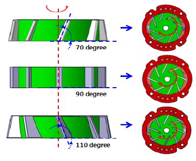
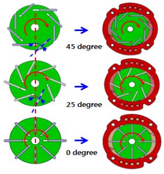
진공펌프 내부의 유동과 구조 성능을 비교하기 위해 베인의 눕힘 각과 회전각 형상을 설계변수로 선정하였으며 이에 대한 각각의 해석을 수행하였다. 설계 변수는 베인의 각도에 따른 성능의 변화추이를 확인하기 위하여 큰 수준의 변수를 임의로 선정하였다. 베인 각도의 눕힘각 변수는 Fig. 1에 나타낸바와 같이 로터 바닥을 기준으로 기울어진 각을 나타낸 것으로, 70 °, 90 °, 110 °이다. 회전각 변수는 Fig. 2에 도시한 바와 같이 진공 펌프가 구동 시 베인의 선단부와 로터의 중심이 이루는 각을 나타낸 것으로, 45 °, 25 °, 0 °이다.
2.2 내부유동 해석조건
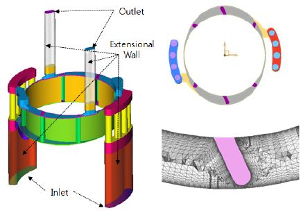
해석을 위하여 펌프의 회전을 가정한 다중 좌표계(MRF)기법을 적용하였으며 요소 모델은 Fig. 3과 같이 펌프의 유로를 가시화하여 유동 영역을 별도로 모델링하였다. 또한 펌프 구동시 입구와 출구에서 유체가 역류하는 것을 방지하고 수치적 해 수렴성을 확보하기 위하여 가상의 벽을 생성하였다.
유동 조건으로는 펌프 내부의 유체 특성이 시간에 따라 변하지 않는 정상 상태로 가정하였고, 난류 유동해석을 위해 Spalart Allmaras 모델을 적용하였다. 펌프 내부로 입력되는 유체 조건으로는 Table 1과 같이 Inlet부에 질량유량을 부여하고 Outlet부에는 대기압을 부여하였으며 로터의 회전 조건으로는 펌프가 안정적으로 최대 부압이 일어나는 회전 속도를 채택하였다. 해석 프로그램은 열유동 해석 소프트웨어인 Altair 社의 Acusolve를 사용하여 유동 특성을 파악하였다.6) 종래의 유한체적 기법을 기반으로 한 CFD 프로그램들과 달리 Acusolve는 격자의 형상 및 품질에 대한 영향이 없으므로 빠른 결과를 산출 할 수 있었다.
2.3 내부유동 결과 분석
펌프 내부의 요소 모델링과 유동해석 조건을 이용하여 내부 유동해석 결과를 도출하였다. 해석결과는 Fig. 4에 도시한 바와 같이 5mm 간격으로 단면의 유체 압력과 유체 속도를 도출하였다. 도출된 결과는 Table 2와 Table 3과 같이 설계 변수에 따른 유체 속도와 Table 4와 Table 5와 같이 유체 압력으로 나타내었다.
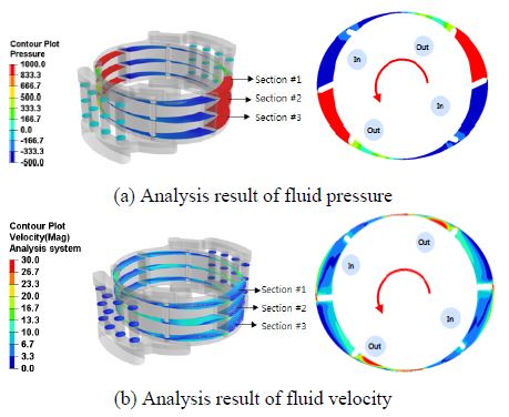
Description of computational fluid dynamics analysis result during the vane type vacuum pump operation

Change of the fluid velocity according to rotating angle parameter from the computational fluid dynamics analysis

Change of the fluid velocity according to tilting angle parameter from the computational fluid dynamics analysis

Change of the fluid pressure according to rotating angle parameter from the computational fluid dynamics analysis

Change of the fluid pressure according to tilting angle parameter from the computational fluid dynamics analysis
눕힘각 90°일 때 유체특성은 다른 설계 변수와 비교하여 유체의 속도가 빠르고 압력이 크게 나타났으며, 회전각 25°일 때 유체의 속도가 다른 설계 변수에 비해 빠르고 압력이 크게 나타남을 알 수 있었다. 이는 다른 각도에 대한 설계변수 대비하여 토출 직전의 유체실의 체적이 작게 형성되어 이에 따라 유속이 빨라지고 압력이 크게 나타나는 것으로 판단된다.
3. 유동-구조 연성 해석
3.1 해석 조건
유동해석에서 도출된 유동 압력을 베인과 로터에 매핑하여 구조해석을 진행하였다. 요소 모델은 Fig. 5에 도시한 바와 같이 유동해석의 베인과 로터의 벽면 요소들을 활용하여 요소 모델링을 하고, 유동 압력을 요소 단위로 부여하였다. 베인과 로터는 Table 6과 같이 탄소・흑연질 물성을 적용하여 로터와 베인이 회전 시 유체 압력에 의한 구조 강도를 도출하였다. 유동 해석에서 수행하였던 설계 변수와 범위를 동일하게 적용하여 변수별 유동압력이 베인과 로터에 미치는 영향을 분석하였다.
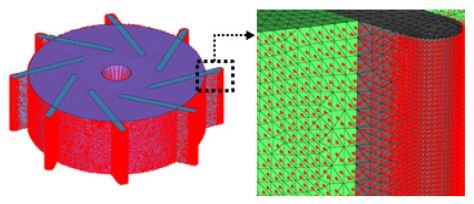
Schematic illustration of pressure mapping the finite element model from the computational fluid dynamics analysis result
3.2 유동-구조 연성해석 결과
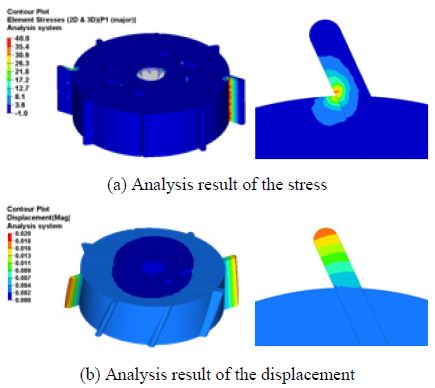
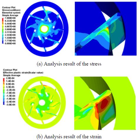
베인과 로터의 설계 변수에 따른 구조해석을 수행하여 유동압력에 의한 응력과 변위를 Fig. 6에 도시한 바와 같이 도출하였다. 회전각 설계 변수는 Table 7에 나타낸 바와 같이 25°설계 변수가 다른 변수들에 비해 응력이 가장 높게 도출 되었으며 45°설계 변수에서는 변위가 가장 크게 도출 되었다. 또한 눕힘각 설계 변수는 Table 8에 도시한 바와 같이 90°설계 변수가 다른 변수들과 비교하여 응력과 변위가 가장 크게 도출되었다. 이는 펌프 내부 유동해석에서 도출 된 유동압력을 구조해석을 위하여 매핑하였으므로, 설계 변수에 따른 유동 압력의 차이가 구조 성능에 직접적으로 영향을 미치기 때문이다. 구조해석에서 도출된 응력을 분석한 결과, 안전강도 대비하여 0.3 % 수준으로써 유동 압력이 탄소 흑연질 물질인 베인과 로터의 구조 성능에 미치는 영향은 매우 작은 것으로 확인되었다.

Change of the stress and displacement according to rotating angle parameter from the structure analysis
4. 펌프 구동에 의한 회전체 해석
4.1 해석 조건
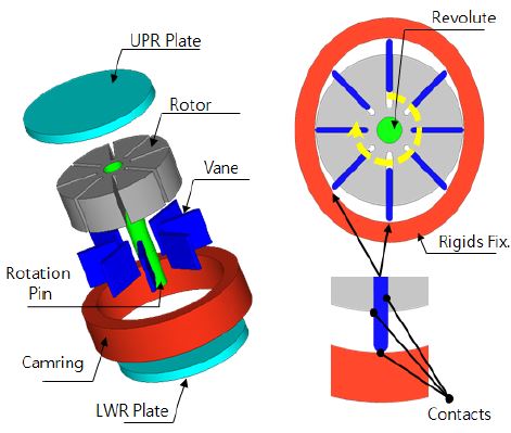
진공펌프의 내부 구동은 회전축에 연결된 로터와 베인이 빠르게 회전하는 구조이다. 이때, 원심력에 의하여 베인이 로터에서 빠져나와 캠링과 접촉하여 회전하게 되는 조건이다.
따라서 펌프 회전에 의한 단품들간의 운동학적 거동을 고려한 구조안정성 확인을 진행하였다. 해석 소요시간을 감안하여 비유동 조건에서 진행되었으며 회전 속도는 앞서 유동해석에서 적용된 4,500 rpm으로 선정하였다. 접촉 조건은 회전축과 로터, 로터와 베인, 베인과 캠링에 각각 부여하고 적용된 소재의 물성은 로터와 베인의 경우, 탄소 흑연질 물성을 적용하였으며 회전축과 캠링 및 다른 단품은 강체로 적용하였다. 또한 고속회전속도에 의한 요소간의 침범현상을 방지하고 베인의 선단부와 캠링의 습동면 사이의 접촉을 안정적으로 적용하기 위하여 해석 모델에 적절한 감쇠 상수를 적용하였다. 회전체의 경계 조건은 Fig. 7에 도시하였다.
4.2 회전체 해석 결과
로터와 베인의 회전에 의한 구조 성능을 도출하기 위하여 펌프 회전 중 발생되는 응력과 변형율을 설계 변수별로 비교하였다. 회전각 설계 변수에 대한 회전체 해석 결과로는 Table 9와 같이 25°의 설계 변수가 다른 변수와 비교하여 상대적으로 응력과 변형율이 낮게 나타났으며 허용치를 만족하였다. 또한 눕힘각 설계 변수에 대한 회전체 해석 결과, Table 10과 같이 90°의 설계 변수가 다른 변수에 비해 상대적으로 응력과 변형율이 낮게 나타났으며 허용치를 만족하였다. 그러나 110°와 70°조건의 응력과 변형율은 허용응력(16 MPa)을 초과하여 나타났다. 눕힘각이 적용된 베인은 캠링과 접촉하는 선단부의 선접촉 길이가 증가하여응력이 크게 나타난 것으로 판단된다.
따라서 베인의 선단부와 캠링의 습동면은 원심력에 의하여 회전 중 마찰이 발생하게 되고 회전반대 방향으로 작용하는 습동면의 마찰력에 의하여 로터 가장자리의 구조 성능이 저하되는 것을 Fig. 8에 도시한 바와 같이 확인할 수 있었다.
5. 결 론
본 연구에서는 전기자동차 시장의 활성화로 인한 전동식 진공펌프의 확대 적용에 대비하여 이에 대한 성능향상을 위한 최적화 방안 모색을 목표로 진행하였으며 이를 위하여 내부유동과 구조성능 분석을 통하여 설계변수별 영향도를 조사하였다.
전동식 진공펌프의 성능은 펌프 내부 구조의 유동 성능과 펌프 구동 시 유체의 속도와 압력 차이에 따른 것임을 확인할 수 있었으며 이에 대한 값을 내부 구조에 매핑한 결과, 펌프 유동압력은 로터와 베인의 구조성능에 미치는 영향이 거의 없는 것으로 확인되었다. 또한 비유동 조건에서 회전체 구동에 의해 발생되는 응력과 변형률을 조사한 결과, 원심력과 베인의 구동 마찰은 로터와 베인의 구조성능에 직접적인 영향을 미치는 중요한 인자임을 확인하였다.
Acknowledgments
A part of this paper was presented at the KSAE 2016 Fall Conference and Exhibition
본 연구는 한국산업단지공단의 친환경 보급형 전기자동차 생산기반 구축을 위한 테마클러스터사업[R&D] 과제로 수행되었으며 (주)화신 기술연구소 관계자들과의 협조를 받아 수행되었으며 이에 감사드립니다.
References
- J. Y. Lee, H. K. Lee, H. S. Heo, B. S. Hwang, J. M. Lee, and H. K. Kim, “Analytical Study on the Vane Type Binary Brake Vacuum Pump”, KSAE Spring Conference Proceedings, p84-88, (2015).
- S. E. Hong, and G. H. Son, “Numerical Study of Three-dimensional 2-phase Flows in a Vane Vacuum Pump”, KSCFE Fall Conference Proceedings, p75-76, (2015).
-
S. H. Lee, and N. K. Hur, “Numerical Study on Effects of Design Factors on Flow Characteristics of a Vane Pump”, Transaction of KSFM, Vol.10(No.6), p24-31, (2007).
[https://doi.org/10.5293/kfma.2007.10.6.024]

- M. S. Kwak, H. H. Cho, and J. B. Kim, “Analytical Study on Performance Characteristics of Variable Vain Type Pump for Automobile Oil”, KSME Fall Conference Proceedings, p37-40, (2012).
-
T. E. Kim, and K. B. Lee, “Numerical Analysis of Flow Fields for Optimum Design of Vehicle Vacuum Pump with Multivanes”, Transaction of KSME, Vol.35(No.9), p883-890, (2011).
[https://doi.org/10.3795/ksme-b.2011.35.9.883]

- Altair Engineering, Acusolve Commands Reference Manual, (2015).
- T. K. Son, G. D. Lee, and J. D. Rho, “Analytical Study on the Fluid-Structure Interaction Vane Type Vacuum Pump”, KSAE Fall Conference Proceedings, p683-684, (2016).
