습식 클러치 체결 마찰 운동에 대한 임계 마찰 성능 평가 방법 연구
Copyright Ⓒ 2024 KSAE / 224-06
This is an Open-Access article distributed under the terms of the Creative Commons Attribution Non-Commercial License(http://creativecommons.org/licenses/by-nc/3.0) which permits unrestricted non-commercial use, distribution, and reproduction in any medium provided the original work is properly cited.
Abstract
The friction performance and the characteristics of a wet clutch operation play a critical role in the design and in the performance evaluation of wet clutch modules in automobile power transfer systems. The functionality of a wet clutch relies on frictional interactions from the combined physical contacts among the wet friction plate, separator plate, and automatic transmission oil. These interactions are limited by the frictional kinetic energy capacity of the system. Each wet clutch combination has specific frictional kinetic energy limits. Exceeding these limits can lead to critical abnormalities and system failures. As wet clutches are essential in power transfer, it is imperative to determine and define the frictional kinetic energy limit characteristics quantitatively. This can be achieved through testing by using the SAE No.2 test device. We conducted tests to verify the frictional kinetic energy limit of a wet clutch. Particularly, we explored the limits under inertial braking and continuous friction operating conditions, the representative operating conditions of the wet clutch. Based on these test results, we presented a comprehensive test methodology that defines quantitative limit ranges for the frictional kinetic energy limit characteristics of wet clutches.
Keywords:
Wet friction plate, Wet separate plate, Wet friction performance, SAE No.2, Friction coefficient, Kinetic friction energy키워드:
습식 마찰판, 분리판, 습식 마찰 특성, 습식 마찰 시험 장치, 마찰계수, 마찰 운동 에너지1. 서 론
최근의 자동차 산업에 요구되는 다양한 소비자의 요구와 함께 세계 정부와 기관들의 기후 환경 문제에 대한 관심으로 지구 온난화 현상에 대한 우려와 예방을 위한 노력이 확대되고 있다. 이러한 노력들은 자동차 산업과 파워트레인(Powertrain) 장치 기술의 개발과 발전으로 현재는 하이브리드, 전기자동차로의 급격한 패러다임(Paradigm) 변화를 수용하고 발전시켜 가고 있다. 이와 함께 파워트레인 기술은 동력원의 변화뿐 아니라 동력 전달의 효율을 높이고 안정적인 구동력 전달과 운전의 편의를 위해 발전되어 왔다. 이러한 기능을 위한 핵심 요소로 습식 클러치(Wet clutch) 및 브레이크(Brake)가 요구되며, 중요한 동력 전달 장치의 기능 요소 부품들이다. 이러한 습식 클러치 및 브레이크는 파워트레인의 전동화(Electrification)로의 변화에도 지속적으로 요구되는 핵심 기능을 담당할 것이다.1) 그러므로 습식 클러치 및 브레이크에 대한 마찰 특성 및 성능 시험 및 평가 방법 또한 고도화 되어야 할 것이며, 본 연구에서는 다양한 습식 마찰 특성 및 성능을 대표할 수 있는 마찰 운동 에너지(Kinetic frictional energy) 특성에 대한 포괄적 시험 및 평가 방법론을 제시한다.
2. 습식 마찰 시스템의 구성
2.1 클러치, 브레이크의 일반적 구성
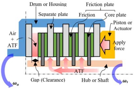
자동차 파워트레인을 사용되는 습식 마찰 시스템(Wet Friction System)의 클러치와 브레이크 장치들은 일반적으로 Fig. 1과 같이 구성된다. 이러한 클러치는 주로 입력된 동력을 전달하는 기능으로 작동하고, 브레이크는 입력된 동력을 출력하지 않고 제동하는 기능으로 작동한다.
또한 최근에는 연속적인 마찰 운동으로 동력 흐름을 제어하는 연속 마찰 제어(Continuous Slip Control)기능으로 널리 활용되고 있다.2,3)
본 연구에서 수행한 관성 제동식 습식 클러치 시험 평가는 습식 마찰 시스템의 기능인 입, 출력 동력의 동기화(Synchronization) 거동을 모사하고 연속 마찰식 시험 평가 방법은 습식 클러치, 브레이크의 체결 마찰력을 초과하는 인가 동력으로 발생되는 미끄러짐 거동의 마찰 특성을 모사하여 평가하였다.
2.2 SAE No.2 시험 장치의 구성
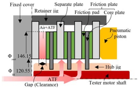
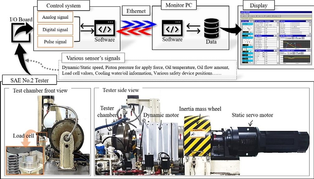
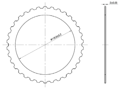
습식 마찰 시스템의 마찰 특성 시험, 평가 방법은 미국 자동차 기술자 학회(SAE, Society of Automotive Engineers)의 SAE J2867) 규격 시험 장치인 SAE No.2 시험 장치를 활용하여 시험 및 평가한다. 이러한 SAE No.2 시험 장치는 Fig. 2와 같은 구성을 갖으며, 본 연구에서 활용된 시험 장치는 Photo. 1과 같은 구성과 Table 1의 사양이다.4-6)
3. 습식클러치 체결 마찰
3.1 측정마찰계수 산정
마찰면(Friction surface)에 발생하는 마찰력 Ff에 대한 마찰 계수는 마찰면에 작용하는 하중(Normal force) fn에 대하여 식 (3.1)과 같이 정의된다.
| (3.1) |
| (3.2) |
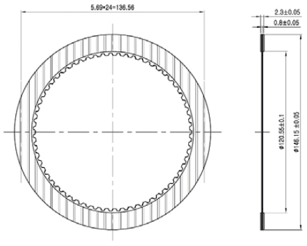
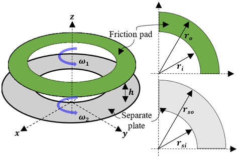
습식 마찰 시스템의 마찰면은 원통 형태로, Fig. 5의 마찰 패드와 분리판이 접촉하여 형성된다. 이러한 원통형 마찰면에서 발생하는 마찰 크기의 측정값인 토크 는 방정식 (3.2)와 같이 표현할 수 있다.
Fig. 5의 ro, ri는 각각 마찰 패드의 내, 외측 반경을 나타내고, rso, rsi는 분리판의 내, 외측 반경을 나타낸다. 또한 ω1, ω2는 각각 마찰 패드의 각속도와 분리판의 각속도이며, h는 마찰 패드와 분리판 사이의 거리이다. 이러한 마찰면의 유효 반경 reff는 식 (3.3)으로 계산할 수 있다.
| (3.3) |
마찰계수 μf를 마찰 정의 산술식으로 계산할 수 있으며, 식 (3.4)와 같이 표현할 수 있다.8-10)
| (3.4) |
3.2 관성 제동식 마찰 운동 에너지 모델
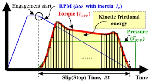
SAE No.2 시험 장치를 활용한 관성 제동식 마찰 특성은 브레이크 장치의 제동 메커니즘(Mechanism)과 유사하며, 다양한 조건에서 습식 클러치와 브레이크의 작동으로 인한 제동 특성을 평가하는 시험 방법으로 널리 활용 된다. 이러한 제동 특성은 입력되는 회전 에너지가 제동되며 발생되는 마찰 토크로 출력되는 방법으로 평가된다. Fig. 6은 이러한 입, 출력 마찰 특성 결과 예시이다. Fig. 6의 마찰 운동 에너지 Edy와 관성량(Inertia) Ie는 식 (3.5), (3.6)으로 표현할 수 있다.
| (3.5) |
| (3.6) |
본 연구에서는 이러한 관성 제동식 마찰 운동 에너지 크기를 SAE No.2 시험 장치 관성체의 관성량을 증가시켜 시험품이 클러치의 기능을 상실하지 않고 동적, 정적 마찰 특성을 유지하는 에너지 조건을 검증하는 시험 및 평가 방법론을 제시한다.5,8,9)
3.3 연속 마찰식 습식클러치 마찰 운동 에너지 수학적 모델
본 연구에서 SAE No.2 시험 장치로 수행한 연속 마찰식 마찰 운동 에너지 시험은 SAE J16465) 규격의 정적 마찰 특성 시험 방법을 응용한 조건이다.
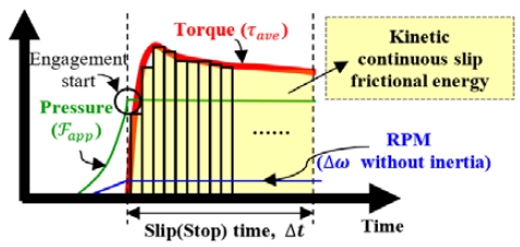
정적 마찰 특성은 관성 제동식 마찰 특성과 달리 클러치 또는 브레이크를 체결 시킨 이후에 입력 회전을 인가하여 체결된 마찰면의 미끄러짐을 발생시킨다. 이때 출력되는 미끄러짐 마찰 토크 특성을 평가하며, Fig. 7은 정적 마찰 특성 결과 예시이다. 이러한 정적 마찰 특성 시험 방법을 응용하여, Fig. 7의 ∆t 동안 연속적인 미끄러짐 마찰이 발생되는 시간을 변수로 하는 마찰 운동 에너지를 구할 수 있으며 방정식 (3.7)로 계산할 수 있다.11,12)
| (3.7) |
본 연구에서 활용된 SAE No.2 시험 장치는 Table 1의 사양에 따라, 최대 150 rpm의 정적 마찰 특성 조건의 회전수를 인가하여 연속적 마찰을 수행할 수 있다.
4. SAE No.2 습식클러치 임계마찰 운동에너지 시험
4.1 습식클러치 SAE J2487 규정 시험 조건
SAE J2487 규정의 시험 조건은 Table 3과 같이 정리 할 수 있다. 이 시험은 관성 제동식 마찰 조건을 200회 반복 수행하고 200회 완료 후 1회의 정적 마찰 조건 시험을 수행하는 조건을 하나의 단계로 구분하여 마찰 운동 에너지 단계별 작동을 수행한다.
관성 제동식 마찰 시험은 Fig. 2의 SAE No.2 시험장치의 구성과 같이 배열된 시험품 조합중 시험 장치의 축과 조립된 마찰판이 회전하고 조정이 가능한 시험 장치의 공압 피스톤 장치의 전진 작동으로 분리판과 접촉 체결하여 제동된다. 이때 발생하는 제동 토크는 Photo. 1의 로드셀(Load cell)을 통해 계측되고 시험 장치의 축과 연결된 ‘Inertia mass wheel’부에서 관성량을 조정할 수 있다.
이러한 각 단계의 동적 마찰 조건은 3,600 rpm의 동일한 입력 회전수 조건에 대하여, SAE No.2 시험 장치의 관성량 Ie를 시험 단계마다 증가시켜 시험품 조합의 손상 또는 기능을 상실하는 단계까지 반복 수행하여 그 결과를 확인한다. 이때 시험품의 체결 제동 시간 ∆t를 0.5초로 고정하고 시험 단계마다 증가하는 회전 관성 에너지량의 증분에 대하여 고정된 제동 시간 tstop 조건에 따라서 발생되는 일률(Power)이 증가되는 조건으로 수행된다. 이때의 일률은 식 (4.1)로 계산할 수 있다.9)
| (4.1) |
정적 마찰 시험은 Fig. 2와 같이 배열된 시험품을조정이 가능한 시험 장치의 공압 피스톤 장치의 전진 작동으로 체결한 이후에 Photo. 1의 ‘Static servo motor’를 시험 장치의 축과 연결하여 회전 동력을 입력한다. ‘Static servo motor’는 ‘Dynamic motor’와 달리 높은 토크와 낮은 회전수로 작동하며 정적 마찰 시험 동안 ‘Dynamic motor’는 무부하 상태로 ‘Static servo motor’ 입력 회전으로 시험 장치의 축과 함께 회전한다.
입력 회전이 인가되기 전에 미리 체결된 시험품 조합은 ‘Static servo motor’의 입력 회전으로 미끄러짐이 발행하며 이때 발생하는 미끄러짐 토크를 시험 장치의 로드셀로 계측한다.
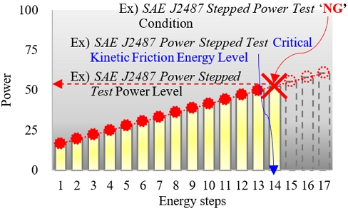
SAE J2487 규정의 시험 결과는 Fig. 8의 예시와 같이 시험품 조합이 기능을 상실하기까지 마찰 운동 에너지 단계에 대한 조건 및 그 크기를 검증할 수 있는 시험평가 방법이다. 이러한 Fig. 8의 ‘NG’조건은 에너지 단계별 시험 수행중 시험품 조합의 기능 이상으로 인한 다양한 마찰 특성 요소가 확인되는 조건을 ‘NG’로 판정 한다.8)
본 연구에서는 각 단계별 시험 과정에서 계측된 대표적인 마찰 특성 요소들인 동적 마찰계수(Dynamic friction coefficient), 정적 마찰 계수(Static friction coefficient), 마찰 계수의 비(Friction coefficient ratio, Endpoint/Midpoint ratio) 결과들의 추이의 급격한 차이가 발생한 시험 회차를 ‘NG’로 판정했으며 각 단계별 시험 완료후 시험품의 마모량 측정 결과들의 추이 이상 및 외관 상태 확인으로 시험품 조합의 기능 상실 여부를 판단하였다. 시험품의 외관 상태는 마찰재의 박리, 탈락 등의 이상 상태 유무 확인과 마찰판, 분리판의 변형 유무 등의 특이 사항을 관찰하여 판단했다.
4.2 관성 제동식 습식클러치 마찰운동 에너지 시험 조건
본 연구에서 제시하는 관성 제동식 임계 마찰 운동 에너지 시험, 평가 방법은 앞서 서술한 SAE J2487 규정의 시험 조건의 주요 독립 변수중 하나인 제동 시간 tstop 조건을 추가하여 그 결과들의 추세선(Trand line)을 통해 마찰 운동 에너지 임계선으로 구분하고자 한다.
본 연구에서는 제동 시간 tstop 조건을 Table 4와 같이 0.5 ~ 2.0초로 확대하였으며, 이러한 관성 제동식 마찰 운동 에너지의 단계 조건 구성을 위하여 시험품 조합의 마찰계수를 0.1로 가정하고 Table 3과 Table 4의 시험 조건들로 확인할 수 있는 변수들을 적용한 식 (3.2), (3.5)과 (4.1)을 계산하였다. 이러한 계산 결과를 시험품 마찰면의 총면적 Ag로 나누어 마찰면 단위 면적당 마찰 운동 에너지와 일률을 계산할 수 있었다. 그 결과는 Table 5와 같다.
Table 5의 ‘Slip time’ 1.0 sec와 2.0 sec 조건의 1 ~ 4단계 및 1 ~ 5단계 일률 조건들은 시험 조건 구현을 위해 필요한 시험 장치의 최소 하중 설정이 불가하다. 해당 조건들은 상대적으로 낮은 일률 조건으로 종합적인 시험 결과에 영향을 미치지 못 조건들로 판단하여 시험 조건에서 제외 하였다.
4.3 연속 마찰식 습식클러치 마찰 운동 에너지 시험 조건
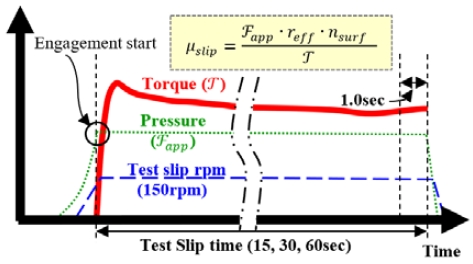
본 연구에서는 SAE No.2 시험 장치로 시험품 조합에 인가할 수 있는 최대 입력 속도인 150 rpm 조건을 적용한 연속 마찰 운동 에너지 단계 조건들을 고려하였다. 이러한 연속 마찰식 운동 에너지 시험 조건은 식 (3.7)에 따라 마찰 시간 동안의 ∆t=tslip 변수를 각각 15, 30, 60초 조건으로 마찰 운동 에너지의 단계를 구성하기 위한 독립 변수들로 설정하였다. 이러한 연속 마찰식 마찰 운동 Eslip에너지에 대한 일률 Powerslip은 아래 식 (4.2)와 같이 표현할 수 있으며, 본 연구에서 수행한 시험으로 측정된 연속 마찰 운동에 대한 토크 와 마찰 계수 μslip은 Fig. 9와 같이 마찰이 종료되기 직전인 tslip -1.0초에서 계측된 토크로 계산된다.
| (4.2) |
또한 연속 마찰식 마찰 운동 에너지에 대한 마찰계수 μslip을 0.1로 가정하고 마찰 운동 에너지와 일률의 계산 결과는 Table 6과 같이 계산될 수 있으며, 시간 변수들에 따라 마찰 운동 에너지를 증가시키고, 체결 하중 Fapp 증가를 위한 압력 조건의 증가에 따라서 일률이 증가되는 조건을 고려한다.
5. 습식클러치 임계마찰 운동 에너지 시험결과
5.1 관성 제동식 습식클러치 마찰 운동 에너지 시험 결과
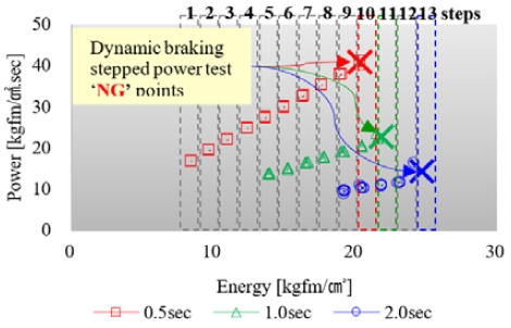
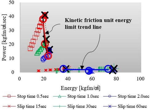
본 연구에서 수행한 시험 결과는 Fig. 10과 같이 확인할 수 있었으며, 관성 제동식 마찰 운동 에너지 시험에 대한 제동 시간 tstop 조건별 마찰 운동 에너지의 임계점들을 확인할 수 있다. 또한 Fig. 11은 각 단계별 시험 수행으로 확인된 마찰 특성 요소들의 추이 결과이며, 시험 종료후 시험품 마찰판 마찰 패드의 박리(Peeling), 눈매움(Glazing), 마모, 분리판의 소성 변형 및 열 손상 흔적(Thermal damage trace) 등의 다양한 외관 이상들이 확인되었다.
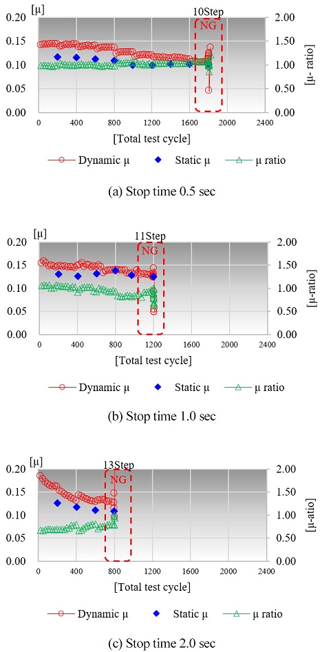
Results of change in friction characteristics at each step of friction kinetic energy by dynamic braking stop time
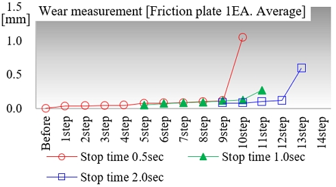
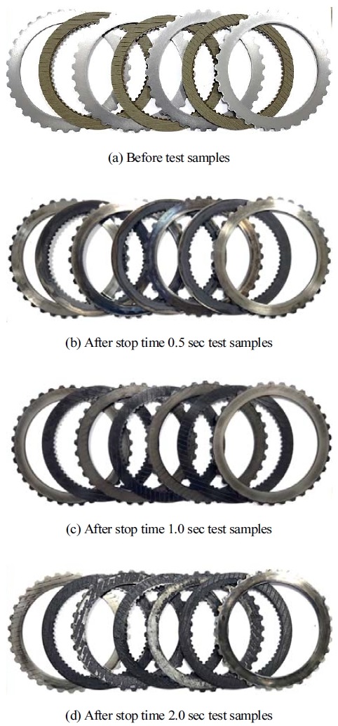
Fig. 12는 각 에너지 단계별 마찰판의 마모량 추이를 확인한 결과로, 마찰판 3매의 평균값으로 산술한 평균 마모량을 나타낸다. 또한 Photo. 2와 같이 시험 전후의 시험품 외관을 비교할 수 있었다.
5.2 연속 마찰식 습식클러치 마찰 운동 에너지 시험 결과
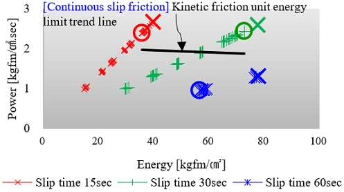
본 연구에서 수행한 연속 마찰식 마찰 운동 에너지 시험, 평가를 마찰 시간을 15, 30, 60초 조건들을 변수로 한 시험 결과들을 확인할 수 있었다. 그 결과는 Fig. 13과 같이 시험 수행 동안 계측된 마찰 특성 요소들의 추이 변화를 확인할 수 있었다. 이러한 추의 변화에서 연속 마찰식 마찰 운동 에너지의 크기가 단계별 증가하는 동안 역전(Reversal)된 결과는 마찰 특성 추이의 이상 확인 및 시험품의 손상 등의 연속 마찰식 마찰 운동 에너지 임계 조건으로 볼 수 있다.
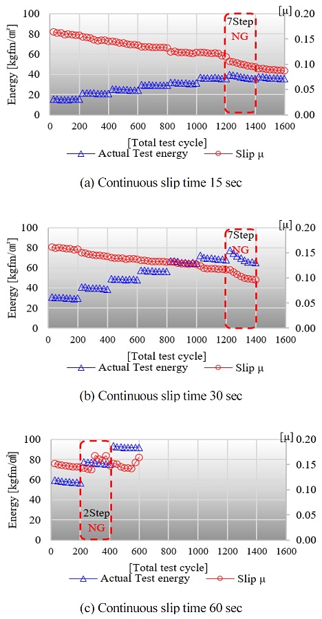
Results of change in friction characteristics at each step of friction kinetic energy by continuous slip time
이러한 이유로 Fig. 14는 연속 마찰 시간 조건별 (15 sec, 30 sec, 60 sec)운동 에너지와 일률과의 관계로 표현한 것으로 연속마찰식 마찰운동에너지 임계 결과들의 추세선으로 구분할 수 있다.
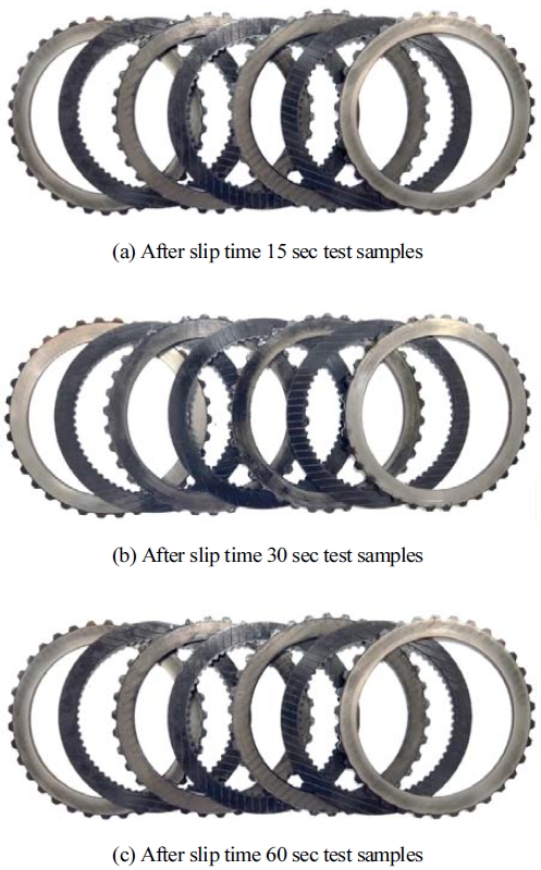
연속 마찰식 마찰 운동 한계 시험을 수행한 시험품 조합의 외관은 Photo. 3과 같으며, 정상 시험품인 Photo. 2 (a)의 시험품 외관과 비교를 통해 시험품의 이상 및 손상 정도를 확인할 수 있었다.
6. 결 론
SAE No.2 시험 장치 및 SAE J2487 규정을 응용하고 확장하여 수행한 본 연구의 시험, 평가 방법으로 습식 클러치 마찰 시스템의 임계 마찰 운동 에너지 한계를 구분하고 그 범위를 판단할 수 있었다.
Nomenclature
| Ag : | gross area |
| Edy : | inertia braking friction kinetic energy |
| Eslip : | continuous slip friction kinetic energy |
| Ff : | friction force |
| : | normal force for contact between friction surface |
| fn : | normal force |
| h : | height between friction pad and separate plate |
| Ie : | inertia |
| nsurf : | number of friction surface |
| Powerdy : | inertia braking power |
| Powerslip : | continuous slip power |
| reff : | effective radius of friction surface |
| ri : | inner radius of friction pad |
| ro : | outer radius of friction pad |
| rsi : | inner radius of separate plate |
| rso : | outer radius of separate plate |
| : | torque |
| τave : | average torque value |
| tslip : | continuous slip time |
| tstop : | stop time |
| μf : | friction coefficient |
| ω : | angular velocity |
| ω1 : | friction pad angular velocity |
| ω2 : | separate plate angular velocity |
| ωi : | input angular velocity |
| ωo : | output angular velocity |
| Φin : | innerdiameteroffrictionsurface |
| Φout : | outerdiameteroffrictionsurface |
Acknowledgments
본 연구에서 활용된 SAE No.2 시험 장치는 ㈜진명프리텍 기술연구소와 2024국민대학교의 지원을 받아 진행한 연구 결과이다.
References
-
Y. Oh and S. Jang, “Study on the Characteristics of Wet Clutch Drag Torque According to Phase of Oil Groove Patterns on Double Side Friction Plate,” Transactions of KSAE, Vol.29, No.12, pp.1073-1082, 2021.
[https://doi.org/10.7467/KSAE.2021.29.12.1073]

-
M. Li, M. M. Khonsari, D. M. C. McCarthy, and J. Lundin, “On the Wear Prediction of the Paper-Based Friction Material in a Wet Clutch,” Wear, Vol.334-335, pp.56-66, 2015.
[https://doi.org/10.1016/j.wear.2015.04.005]

-
L. Yu, B. Ma, M. Chen, H. Li, J. Liu, and M. Li, “Investigation on the Failure Mechanism and Safety Mechanical-Thermal Boundary of a Multi-Disc Clutch,” Engineering Failure Analysis, Vol.103, pp.319-334, 2019.
[https://doi.org/10.1016/j.engfailanal.2019.04.071]

-
W. Ost, P. De Baets, and J. Degrieck, “The Tribological Behavior of Paper Friction Plates for Wet Clutch Application Investigated on SAE#II and Pin-on-Disk Test Rigs,” Wear, Vol.249, pp.361-371, 2001.
[https://doi.org/10.1016/S0043-1648(01)00540-3]

- G. H. Jung, D. H. Park, and D. H. Na, “Experimental Analysis of an Automatic Transmission Clutch Disk Friction Characteristics,” Journal of Drive and Control, Vol.15, No.3, pp.14-20, 2018.
-
H. Haria, G. M. Pietron, J. Meyer, Y. Fujii, P. Wang, and N. Katopodes, “In-Vehicle Characterization of Wet Clutch Engagement Behaviors in Automatic Transmission Systems,” SAE International, Vol.11, No.5, pp.369-375, 2018.
[https://doi.org/10.4271/2018-01-0395]

- “SAE No.2 Clutch Friction Test Machine Guidelines,” SAE International Standard, J286_201203, 2012.
- “SAE No.2 Friction Test Machine 3600rpm Stepped Power Test,” SAE International Standard, J2487_201905, 2019.
- “Glossary of Terms-Lubricated Friction Systems,” SAE International Standard, J1646_201203, 2012.
-
J. Cho, Y. Lee, W. Kim, and S. Jang, “Wet Single Clutch Engagement Behaviors in the Dual-Clutch Transmission System,” Int. J. Automotive Technology, Vol.19, No.3, pp.463-472, 2018.
[https://doi.org/10.1007/s12239-018-0045-9]

-
A. Higashimata, K. Adachi, S. Segawa, N. Kurogo, and H. Waki, “Development of a Slip Control System for a Lock-Up Clutch,” SAE 2004-01-1227, 2004.
[https://doi.org/10.4271/2004-01-1227]

-
Y. Katsumata, S. Segawa, K. Adachi, and A. Higashimata, “Development of a Slip Speed Control System for a Lock-Up Clutch (Part II),” SAE 2008-01-0001, 2008.
[https://doi.org/10.4271/2008-01-0001]

