Development of Vehicle Roll Rate Estimator Using Transfer Function Estimation
Copyright Ⓒ 2022 KSAE / 194-01
This is an Open-Access article distributed under the terms of the Creative Commons Attribution Non-Commercial License(http://creativecommons.org/licenses/by-nc/3.0) which permits unrestricted non-commercial use, distribution, and reproduction in any medium provided the original work is properly cited.
Abstract
An accurate measurement of the roll angle or roll rate is important in RSC(Roll Stability Control) research. It can be measured directly only with expensive measuring equipment like INS(Inertial Navigation System) or dual-antenna GPS. Moreover, the estimation approach requires vehicle parameters, including cornering stiffness, spring coefficient, and damping coefficient. This paper proposes a technique to estimate roll rate without vehicle parameter information through transfer function estimation. By using dynamic models, a transfer function is derived to describe the relation between the roll rate and the yaw rate. Driving data for step steer, double lane change, lane change, and sine sweep scenarios are used, and a multi-model estimator is designed to secure estimation performance at various speeds. The proposed method is verified by simulation and real vehicle experiments.
Keywords:
Roll rate, Transfer function, Estimator, Vehicle dynamics, Driving safety1. Introduction
With the development of vehicle electrification technology, there is a growing expectation from consumers for standards of electronic control safety, driver assistance systems and autonomous driving technology suitable for specific driving scenarios. In line with this trend, driving safety, which is directly related to the lives of passengers, has naturally become a key issue in the automobile industry. The rollover phenomenon of a vehicle, in particular, greatly threatens driving safety. This occurs quite frequently during traffic accidents, and causes fatal injuries in most situations.1) Thus, efforts continue to be made to research and develop Roll Stability Control(RSC) to prevent rollover.2-5) Yuan et al.2) conducted a study to prevent rollover phenomenon using model-based torque vectoring control, while Riofrio et al.3) conducted a study to implement RSC using an LQR(Linear Quadratic Regulator)-based active suspension controller. As such, RSC research using various methods is progressively underway. In addition, in vehicles with a relatively high roll center, such as SUVs, roll motion influences ride comfort, so RSC has become an important research field in terms of vehicle safety as well as ride comfort.
Accurate measurement and estimation of roll angle or roll rate are essential for RSC research and development, which can be measured directly using expensive measurement equipment such as INN or dual-antenna GPS.6) Accordingly, research on roll estimation techniques is being actively carried out, and they are largely divided into a method using a model-based state estimator and an estimation method using sensor fusion.
A Kalman filter based on roll dynamics is generally designed in developing a model-based roll state estimator.7,8) On the other hand, since the general Kalman filter assumes linear dynamics, it is not suitable as a state estimator when roll dynamics involving nonlinearity are adopted. To solve this problem, estimation methods have been proposed using linear roll dynamics or EKF(Extended Kalman Filter) and UKF(Unscented Kalman Filter) that can be used for nonlinear models.9,10) However, these methods pose the disadvantage of needing to know vehicle parameters such as cornering stiffness, roll center height, spring coefficient, and damping coefficient, making it difficult to use them in situations where such vehicle specifications are not known.
There is also a sensor combination method using various sensors commonly used in vehicles. Jiang et al11) proposed a method for estimating roll using a combination of an accelerometer and a suspension deflection sensor. There is also a sensor combination method using various sensors commonly used in vehicles. However, since the suspension deflection sensor is expensive and it is not generally attached to mass-produced vehicles, its universal use is difficult. Although research has been conducted to converge low-cost GPS sensors and sensors commonly attached to vehicles, such as IMUs(Inertial Measurement Units),12) in the case of a GPS sensor, the method poses of the risk of possible errors occurring greatly in an environment that affects the signal of a satellite, such as a situation in a city center with high-rise buildings.
This study proposes an estimation technique that simulates roll motion using only vehicle experimental data without vehicle specification information. The roll rate output transfer function for the yaw rate input was derived using a dynamic model, and a multi-model estimator for each speed was designed to improve the estimation accuracy. The performance of the proposed algorithm has been verified through simulation and actual vehicle experiments. Its estimation performance was quantitatively expressed through RMSE(Root Mean Square Error) evaluation.
2. Modeling
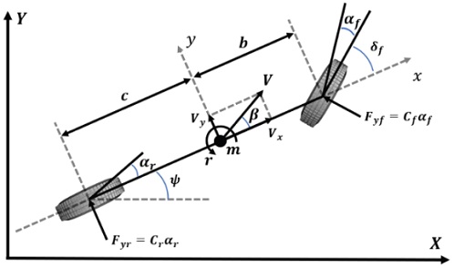
This section describes the process of expressing and combining the yaw rate motion and roll rate motion of a vehicle in the form of a transfer function. To make the roll rate output model for the yaw rate input, the 2-dof bicycle model was used for the yaw rate motion model, while the approximated roll plane model was used for the roll rate motion model.
| (1) |
where,
| (2) |
where
A transfer function represents the relationship between the system input and output, and can relatively simplify complex expressions. In particular, the transfer function has the advantage that it can be expressed in a desired form by transforming it in such a way that it erases the input and output of the derived system.
Converting Equations (1) and (2) into a transfer function form is as carried out as follows. Equation (3), which is the yaw rate output for steering input from the 2-dof bicycle model, and Equation (4), which is the roll rate output for lateral acceleration input from the approximated roll plane model, can be obtained.
| (3) |
where
| (4) |
where
| (5) |
Using Equation (1) and Equation (5), the lateral acceleration output for the steering input can be expressed as follows.
| (6) |
In Equation (6), can be expressed as follows by removing the common elements of and and multiplying them.
| (7) |
where
By expanding the obtained expression, the transfer function can be calculated as follows.
| (8) |
where
The model can be expressed in the form of a transfer function having 3 poles and 3 zeros. In this paper, a transfer function expressing the roll rate was derived based on these physical expressions.
3. Model Identification
This section describes the process of identifying the transfer function model using the driving data.
3.1 Vehicle Dataset Selection and Model Identification
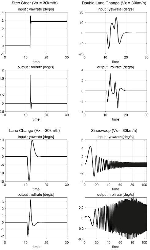
To improve the accuracy of the roll rate model in various situations, driving data for step steer, double lane change, lane change, and sinesweep scenarios were used. Fig. 3 below presents sample driving data for 30 km/h speed.
In order to express a change in roll rate with respect to the yaw rate as a model, 15 data sets were merged for each speed from 30 km/h to 100 km/h. Thus, a total of 150 data sets were used as working data. The experimental data sets were implemented through commercial software CarSim,13) while model identification was performed using the System Identification tool of MATLAB.14)
3.2 Multi-model Estimator Design by Speed
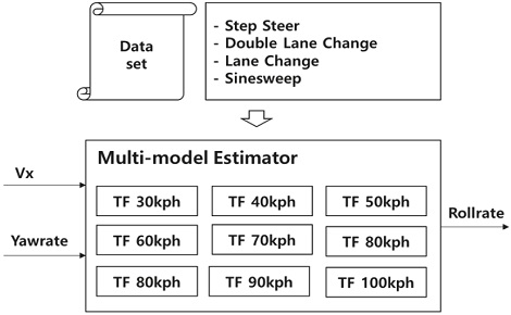
A difference occurs between yaw motion and roll motion based on speed. Thus, the roll rate estimation accuracy was improved by designing a multi-model estimator for each speed using the previously generated transfer function model. The conceptual diagram for this is shown in Fig. 4 below. By varying the model for each speed, an estimator that uses the vehicle’s yaw rate and Vx as inputs was designed.
4. Discussion
This section deals with model identification results, simulation verification results, and actual vehicle test results. In order to verify the performance of the proposed estimator, simulation and actual vehicle experiments were conducted. Simulation verification was performed through scenarios not included in the 150 data sets used for transfer function identification and through CarSim’s Handling Course driving scenarios.
4.1 Model Identification Results
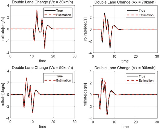
The transfer function results obtained by collecting driving data for each speed mentioned in 3.1 are as follows. For the double lane change scenario with the largest amplitude among driving data, the speed of 30 km/h, 50 km/h, 70 km/h, and 90 km/h are shown below.
It was confirmed that the model identified in the form of 3 poles and 3 zeros in the proposed Equation 8 simulates the roll rate well. Therefore, it was considered possible to design a roll rate estimator with excellent performance using only experimental data.
4.2 Simulation Results
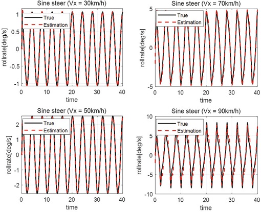
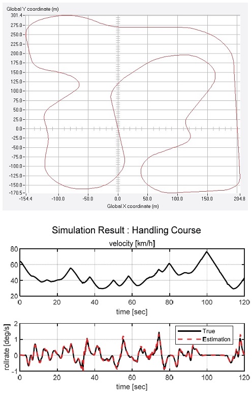
To check the estimation performance in more diverse situations, the estimation performance in the sine steer scenario not included in the working data was checked. Simulation verification of driving at various speeds in CarSim’s handling course with various curvatures was also performed.
As a result of the verification, it was confirmed that the roll rate estimation performance of the estimator was excellent even in the sine steer scenario, which was not used for transfer function identification. The performance of the multi-model estimator was confirmed by confirming that the estimator was working well even when the speed changed.
It was also confirmed that excellent estimation results were obtained even when driving at various speeds and various curvatures, as shown in Fig. 7 The RMSE value in the handling course was 0.0764, which quantitatively verified that the estimator for the roll rate works well. Thus, the effectiveness of the estimator designed and proposed in this study using only experimental data without knowing the spring coefficient and damping coefficient was confirmed.
4.3 Actual Vehicle Test Results
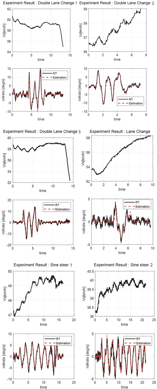
An actual vehicle experiment was performed to check whether the proposed logic works well. The roll rate estimator was designed using the same process as the previous simulation. For real-time algorithm implementation, dSpace’s Micro Autobox was used, while OxTS’ RT3000 was used for the measurement. For logging of the experimental results, Vector’s CANoe equipment was used. RMSE was used to quantify the estimation error of the experimental results, while the square root was obtained by dividing the sum of the squared errors of each step by the number of samples. The definition for this is shown in Equation (9) below. The RMSE values for each scenario are summarized in Table 2, and if it is less than 1.3, it is assessed to be appropriate.15)
| (9) |
Results of the experiment confirmed that the proposed roll rate estimator works well in real vehicles since the RMSE values are sufficiently small.
5. Conclusion
In this study, an estimator was designed for estimating the roll rate when spring coefficient and damping coefficient values are not given and using the transfer function estimation technique. Using driving data for step steer, double lane change, lane change, and sinesweep scenarios, a transfer function with yaw rate as input and roll rate as output was obtained for each speed. A multi-model estimator was also designed to secure estimation performance at various speeds.
Through simulation verification, the effectiveness of the methodology proposed in this paper was confirmed. The difference between the value measured at RT and the proposed algorithm was quantified as RMSE through the actual vehicle experiment, proving that the roll rate estimation algorithm works well in real vehicles.
Based on the algorithm for estimating the roll rate with only the Vx and yaw rates that can be measured in general vehicles, the proposed algorithm can be used as an alternative when vehicle specification information about the values of spring coefficient and damping coefficient is insufficient or cannot be measured.
Nomenclature
| a : | acceleration expressed in inertial coordinate system, m/s2 |
| α : | lateral slip angle at tire, rad |
| V : | velocity expressed in inertial coordinate system, m/s |
| r : | yaw-rate expressed in inertial coordinate system, rad/s |
| C : | cornering stiffness of tire, N/rad |
| m : | total vehicle mass, kg |
| ms : | vehicle sprung mass, kg |
| I : | mass moment of inertia, kgm2 |
| b : | distance from front wheel center to mass center, m |
| c : | distance from rear wheel center to mass center, m |
| δ : | wheel steer angle, rad |
| Φ : | roll angle of sprung mass, rad |
| hcr : | distance from the sprung mass center to the roll center, m |
| g : | gravitational acceleration, m/s2 |
| KΦ : | total torsional stiffness of suspension, Nm/rad |
| CΦ : | total torsional damping of suspension, Nms/rad |
Subscripts
| f, r : | front/rear |
| x, y, z : | longitudinal/lateral/vertical direction |
Acknowledgments
This study was conducted as a result of the research project “Development of autonomous driving system and evaluation verification technology for large buses” of the Korea Evaluation Institute of Industrial Technology (20006862).
References
-
R. Rajamani and D. Piyabongkarn, “New Paradigms for the Integration of Yaw Stability and Rollover Prevention Functions in Vehicle Stability Control,” IEEE Transactions on Intelligent Transportation Systems, Vol.14, No.1, pp.249-261, 2012.
[https://doi.org/10.1109/TITS.2012.2215856]

-
H. Yuan, D. Zhang and T. Gordon, “Road Vehicle Rollover Prevention Torque Vectoring via Model Predictive Control,” Chinese Control Conference, pp.9401-9406, 2017.
[https://doi.org/10.23919/ChiCC.2017.8028856]

-
A. Riofrio, S. Sanz, M. Boada and B. Boada, “A LQR-based Controller with Estimation of Road Bank for Improving Vehicle Lateral and Rollover Stability via Active Suspension,” Sensors, Vol.17, No.10, Paper No.2318, 2017.
[https://doi.org/10.3390/s17102318]

-
J. Jo, S. You, J. Joeng, K. Lee and K Yi, “Vehicle Stability Control System for Enhancing Steerabilty, Lateral Stability, and Roll Stability,” Int. J. Automotive Technology, Vol.9, No.5, pp.571-576, 2008.
[https://doi.org/10.1007/s12239-008-0067-9]

-
W. Wang, W. Zhang and Y. Zhao, “Integrated Stability Control Strategy of In-Wheel Motor Driven Electric Bus,” Int. J. Automotive Technology, Vol.21, No.4, pp.919-929, 2020.
[https://doi.org/10.1007/s12239-020-0088-6]

-
B. Boada, M. Boada, L. Melendez and V. Diaz, “A Robust Observer based on H∞ Filtering with Parameter Uncertainties Combined with Neural Networks for Estimation of Vehicle Roll Angle,” Mechanical Systems and Signal Processing, Vol.99, pp.611-623, 2018.
[https://doi.org/10.1016/j.ymssp.2017.06.044]

-
K. Nam, S. Oh, H. Fujimoto and Y. Hori, “Estimation of Sideslip and Roll Angles of Electric Vehicles Using Lateral Tire Force Sensors through RLS and Kalman Filter Approaches,” IEEE Transactions on Industrial Electronics, Vol.60, No.3, pp.988-1000, 2013.
[https://doi.org/10.1109/TIE.2012.2188874]

-
Y. Sebsadji, S. Glaser, S. Mammar and M. Netto, “Vehicle Roll and Road Bank Angles Estimation,” IFAC Proceedings Volumes, Vol.41, No.2, pp.7091-7097, 2008.
[https://doi.org/10.3182/20080706-5-KR-1001.01202]

-
M. Wielitzka, M. Dagen and T. Ortmaier, “Joint Unscented Kalman Filter for State and Parameter Estimation in Vehicle Dynamics,” IEEE Conference on Control Applications, pp.1945-1950, 2015.
[https://doi.org/10.1109/CCA.2015.7320894]

-
G. Jia, L. Li and D. Cao, “Model-based Estimation for Vehicle Dynamics States at the Limit Handling,” Journal of Dynamic Systems, Measurement, and Control, Vol.137, No.10, Article No.104501, 2015.
[https://doi.org/10.1115/1.4030784]

-
G. Jiang, L. Liu, C. Guo, J. Chen, F. Muhammad and X. Miao, “A Novel Fusion Algorithm for Estimation of the Side-slip Angle and the Roll Angle of a Vehicle with Optimized Key Parameters,” Proceedings of the Institution of Mechanical Engineers, Part D: Journal of Automobile Engineering, Vol.231, No.2, pp.161-174, 2017.
[https://doi.org/10.1177/0954407016644879]

-
J. Guo, Y. Luo, K. Li and Y. Dai, “Coordinated Path-following and Direct Yaw-moment Control of Autonomous Electric Vehicles with Sideslip Angle Estimation,” Mechanical Systems and Signal Processing, Vol.105, pp.183-199, 2018.
[https://doi.org/10.1016/j.ymssp.2017.12.018]

- Mechanical Simulation, CarSim Math Models, carsim.com, .
- The MathWorks, MATLAB and Statistics Toolbox Release 2015b, Inc., Natick, Massachusetts, United States.
-
K. Mazhar, M. Khan, A. Bhatti and N. Naseer, “A Novel Roll and Pitch Estimation Approach for a Ground Vehicle Stability Improvement using a Low Cost IMU,” Sensors, Vol.20, No.2, Paper No.340, 2020.
[https://doi.org/10.3390/s20020340]


