디젤 모사 연료 구성 성분에 따른 분무 특성 연구


Copyright Ⓒ 2020 KSAE / 175-06
This is an Open-Access article distributed under the terms of the Creative Commons Attribution Non-Commercial License(http://creativecommons.org/licenses/by-nc/3.0) which permits unrestricted non-commercial use, distribution, and reproduction in any medium provided the original work is properly cited.
Abstract
Diesel has a wide range of hydrocarbon components, which determine the spray evaporation, ignition timing, and rate of combustion. Normal heptane(single component), which has similar CN with diesel, is commonly used for diesel surrogates. However, fuel composition primarily controls the ignition timing and rate of combustion especially in advanced diesel combustion concepts. Therefore, more realistic surrogate models are required to gain a better understanding of advanced diesel combustion concepts such as LTC. The present work develops the multi-component surrogate fuel model of diesel by matching distillation profiles and covering the measured concentrations of the various hydrocarbon classes, to more accurately simulate the spray characteristics of diesel fuel. To investigate the effect of the number of surrogate fuel components, spray and combustion simulations were performed using 1 to 10 components of surrogate fuel models.
Keywords:
Surrogate fuel, Multi-component surrogate fuel, Diesel, Spray, Low temperature combustion키워드:
모사 연료, 다중성분 모사 연료, 디젤, 분무, 저온연소1. 서 론
디젤은 수천 가지 탄화수소로 구성된 복잡한 혼합물이기 때문에 이를 엔진 해석에 그대로 반영하기에는 제약이 있다.1) 모사 연료 모델(Surrogate fuel model) 이란 가솔린, 디젤과 같은 혼합물을 간단하게 표현하기 위한 연료 모델로 가장 간단한 모사 연료 모델은 가솔린을 이소옥탄(Iso-octane)으로 디젤을 노멀헵탄(N-heptane)으로 모사하는 등과 같은 단일 성분 모사 연료 모델(Single-component surrogate fuel model)이다. 지금까지 많은 엔진 해석 연구에서 화학 반응에 소요되는 계산 시간을 줄이기 위해 단일 성분 모사 연료 모델을 많이 사용해왔다.2,3) 하지만 단일 성분 모사 연료 모델로는 실제 연료의 복잡한 증발 현상을 예측하는 데에 한계가 있다. 특히, 냉시동 조건, 저온 연소 등에서는 연료의 자발화 시기, 연소율 등이 연료의 구성 성분에 의해 우선적인 영향을 받기 때문에 보다 정확한 해석 결과를 얻기 위해서는 연료의 구성 성분을 반영해야 한다.4) 모사 연료 모델은 분무에 관련되는 액체 연료의 물리적인 특성을 고려한 “Physical surrogate”, 연소에 관련되는 기화된 연료의 화학적인 특성을 고려한 “Chemical surrogate”로 나눌 수 있다.5-7) 특히 연료의 분사, 분무 분열, 증발은 액체 연료의 물리적인 특성에 의해 결정되기 때문에 연료의 물리적인 특성이 잘 반영된 “Physical surrogate” 모델 개발이 중요하다.8) 지금까지의 다중 성분 디젤 모사 연료 개발은 주로 축소 화학 반응식 개발을 포함하는 “Chemical surrogate” 모델 개발에 관한 연구가 주를 이루었다.2,9,10) 그러나 “Chemical surrogate” 의 경우 구성 성분의 수를 늘리게 되면 그에 따른 추가적인 축소화학반응식의 개발이 필요하고, 전체적인 연료의 화학 반응식이 커지기 때문에 계산 시간이 기하급수적으로 증가하게 된다. 따라서 대부분의 모델에서 그 구성성분의 수가 2 ~ 4개 정도로 구성 성분의 수를 늘리는 데 한계가 있었다. 이러한 한계 때문에 Physical surrogate와 Chemical surrogate의 구성 성분을 다르게 한 Group chemistry representation method 등이 사용되기도 한다.5-7,11)
따라서 본 연구에서는 디젤 연료의 분무 특성을 보다 정확하게 모사하기 위하여, 대한민국에서 판매되고 있는 디젤 연료에 대하여 1 ~ 10 가지 성분으로 구성된 “Physical surrogate” 모델을 개발하고 이들의 분무 및 연소 특성을 해석적으로 고찰하였다.
2. 디젤 모사 연료 개발 및 검증
2.1 연료 모델 개발 및 검증
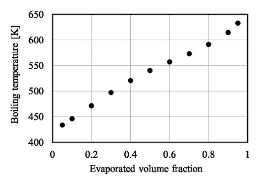
액체 상태의 디젤 연료의 모사 연료 모델은 실제 디젤 연료의 증류 곡선 및 탄화수소 그룹의 성분비 비교를 통하여 개발되었다. 연구에 사용된 디젤 연료는 현재 대한민국에서 판매중인 연료로 포화 탄화수소(Saturate) 77. 4 %, 방향족 탄화수소(Aromatic) 22.6 %로 구성되어 있으며 세탄가(CN, cetane number)는 53.9이다. 디젤 연료의 증류 곡선은 Fig. 1에 나타내었다. 증류 곡선 비교를 통해 모사 연료 구성 성분 비를 결정하는 방법은 Anand의 논문에 자세하게 설명되어 있다.5)
모사 연료의 구성 성분 변화에 따른 분무 및 연소 특성을 살펴보기 위하여, 구성 성분 수를 1, 2, 4, 6, 8, 10 개로 변화 시켰으며 개발된 모델의 구성 성분 및 실제 연료와의 탄화수소 그룹별 성분 비교 결과는 Table 1과 Table 2에 나타내었다. Table 1에서 Surrogate model의 예측 CN 값은 각 성분의 CN 값과 성분의 질량비를 이용하여 평균한 값이다.
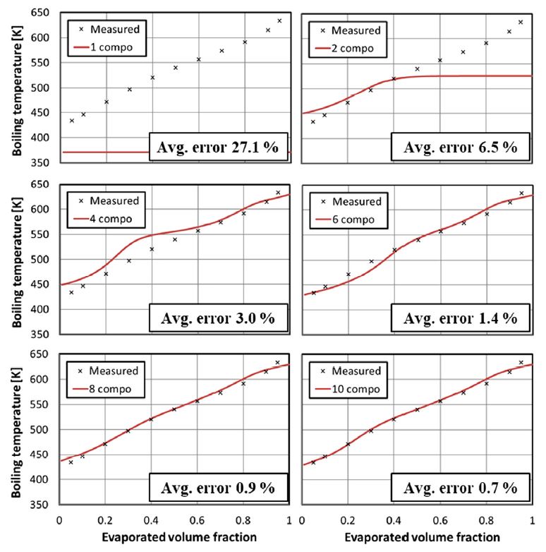
Fig. 2는 개발된 연료 모델의 증발 특성을 측정된 디젤 연료의 증발 특성과 비교한 그래프이다. 구성 성분이 1개인 경우(1 compo)에는 끓는점에서 증발이 시작되어 끝이 나기 때문에 증발 곡선이 직선으로 나타난다. 2개 이상의 성분을 가지는 경우에 증발 곡선이 곡선 형상으로 나타나기 시작하며 성분의 수가 많을수록 실제 디젤 연료의 증발 특성과 유사한 증발 곡선을 가지게 된다. 구성성분 수가 10개인 경우(10 compo) 실제 연료의 증발 특성을 가장 잘 반영하고 있으며 평균 오차는 0.7 %이다.
개발된 연료 모델은 Physical surrogate의 영향만을 고려하기 위하여 액체 연료가 증발되면 노멀헵탄(N-heptane, C7H16)이 되도록 설정하였다. 노멀헵탄은 세탄가가 53으로 디젤과 비슷하여 많은 연구에서 디젤의 모사 연료로 사용되고 있으며, 잘 검증된 축소 화학반응식도 개발되어 있다.
3. 결과 및 고찰
3.1 해석 조건
본 연구에서 개발된 디젤 모사 연료의 구성 성분에 따른 분무 및 연소 특성을 확인하기 위하여 2.2 L 승용 디젤 엔진 운전 조건에서 분무 및 연소 해석을 수행하였다. 사용한 엔진의 사양은 Table 3에 나타내었다. 2000 rpm, bmep 6bar, EGR 30 % 조건에서 해석을 수행하였으며 냉시동 조건 등 낮은 온도에서의 분무 특성을 살펴 보기 위하여 분사되는 연료의 온도 373 K(Normal) 조건과 273 K(Cold) 조건에 대하여 살펴보았다.
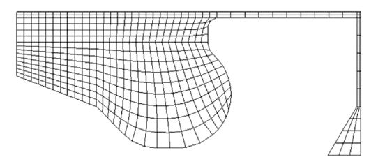
계산에 사용된 격자는 Fig. 3에 나타내었다. 전체 실린더를 인젝터 분공수로 나눈 1/8 sector mesh를 사용하여 흡기 밸브 닫힘부터 배기 밸브 열림 시점까지 계산을 진행하였다. 계산은 인젝터 분공 하나에서 나오는 연료량 (0.021 g의 연료를 분공 수 8로 나눈 값)에 대해 수행 되었으며 계산 결과는 전체 인젝터 8 개 분공에 대한 값으로 환산하여 표시하였다. 계산 격자의 수는 BDC(Bottom Dead Center)에서 약 16,000 개이며, 계산 격자 크기가 결과에 미치는 영향에 대해서는 선행 연구에서 검증된 바 있다.16-18)
3.2 해석 결과 및 고찰
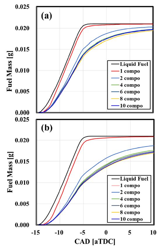
먼저 디젤 모사 연료의 구성 성분에 따른 분무 특성을 확인하기 위하여 연소를 위한 화학반응이 발생하지 않도록 설정하고 해석을 수행하였다. Fig. 4는 액체연료의 분사가 시작되는 시점부터 분사된 액체 연료 및 증발된 기체 연료의 양을 나타낸 그래프이다. 단일 성분 모사 연료 (1 compo) 로 사용된 노멀헵탄의 경우 끓는 점이 약 371 K로 일반 조건이나 저온 조건 모두 대부분의 연료가 증발되었다. 그러나 다중 성분 모사 연료의 경우, 단일 성분 모사 연료의 경우 보다 증발이 더디게 진행되며 그 격차는 저온 분사 조건에서 더욱 커진다.
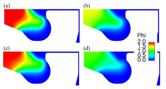
TDC에서 분사된 연료량 대비 증발된 연료량의 비율은 1 compo 모델의 경우 두 조건 모두 98 % 이상의 연료가 증발 된 반면, 10 compo 모델의 경우 일반 조건에서는 약 89 %, 저온 조건에서는 약 66 %의 연료만이 증발되었다. 단일 성분 모사 연료 모델의 경우 단일 온도에서 증발이 시작되지만 다중 성분 모사 연료 모델의 경우 실제 디젤 연료의 증발 특성 (약 430 K ~ 630 K 범위에 걸쳐서 증발이 진행)을 반영하고 있기 때문에 이러한 차이가 발생하게 된다. 특히 저온 조건에서 모델 별 차이가 현저하게 발생하므로 냉시동, 저온 연소 등의 조건을 제대로 반영하여 해석을 진행하기 위해서는 다중 성분 모사 연료 모델이 필요하다고 할 수 있다. 이러한 증발 특성의 차이는 연소 특성에도 그대로 영향을 미치게 된다. Fig. 5는 TDC에서 연소실 내부의 당량비(Phi) 분포를 비교한 그림이다. 연소에 참여하는 것은 기화된 연료이므로 당량비는 증발된 기체 연료량 만을 사용하여 계산되었다. 증발된 연료량의 차이로 인해 1 compo 연료 모델의 경우 연소실 중앙부에 당량비 2 이상의 농후한 영역이 나타나지만 10 compo 연료 모델의 경우 연소실 중앙부의 당량비가 1 ~ 1.5정도로 형성되어 있다. 저온 조건의 경우, 일반 조건 대비 증발된 연료량이 더 적으나 성분 수에 따른 증발 특성은 일반 조건과 유사하게 나타났다. 이러한 성분 수에 따른 증발 특성 차이는 점화 지연 시간 및 배출물 형성에 전혀 다른 결과를 가져올 것으로 예상된다.
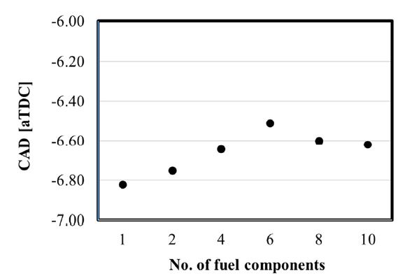
개발된 연료 모델은 Physical surrogate의 영향만을 고려하기 위하여 액체 연료가 증발되면 노멀헵탄(N-heptane, C7H16)이 되도록 설정하였다. 즉, 분무 과정(연료 분사, 분무 분열, 증발)은 다중 성분 모사 연료 모델을 이용해서 계산이 되고, 증발 이후의 화학 반응은 노멀헵탄의 축소화학반응식을 이용해서 계산이 진행되었다. 연료 모델 구성 성분 개수에 따른 연소 시작 시간 비교는 Fig. 6에 나타내었다. 연소 시작 시점은 ECN의 Ignition guideline에 따라 연소실 최고 온도의 상승율이 최대값을 가지는 시점으로 정의하였다.19) 그래프에서 알 수 있듯이 일반 연소 조건에서는 구성성분에 따른 연소 시작 시간 차이가 약 0.3 CAD 내외로 큰 영향을 받지 않는 것을 알 수 있다. 하지만 이 차이는 저온 연소 조건에서 더 크게 나타날 것으로 예상되며, 각 구성 성분의 축소 화학 반응식까지 적용하면 보다 정확한 비교를 할 수 있을 것으로 생각된다. 아직까지 연료 모델 구성 성분들의 축소 화학 반응식이 모두 개발 된 것이 아니므로 Chemistry surrogate 모델까지 적용하기에는 한계가 있다. 이는 향후 연구에서 계속 진행되어야 할 부분이다.
4. 결 론
- 1) 본 연구에서는 디젤 연료의 분무 특성을 보다 정확하게 모사하기 위하여, 디젤 연료에 대하여 1 ~ 10 가지 성분으로 구성된 “Physical surrogate” 모델을 개발하고 이들의 분무 및 연소 특성을 해석적으로 고찰하였다.
- 2) 액체 상태의 디젤 연료의 모사 연료 모델은 실제 디젤 연료의 증류 곡선 및 탄화수소 그룹의 성분비 비교를 통하여 개발되었다. 구성 성분의 수가 많을 수록 실제 디젤 연료의 증발 특성과 유사한 증발 곡선을 가지게 되며. 구성성분 수가 10개인 경우(10 compo) 실제 연료와의 증발 곡선 평균 오차는 0.7 %이다.
- 3) 디젤 모사 연료의 구성 성분에 따른 분무 특성 비교 결과, TDC 시점에서의 증발된 연료량의 차이가 일반 운전 조건에서는 약 15 %, 저온 운전 조건에서는 약 33 %로 나타났다. 따라서 보다 정확한 해석을 진행하기 위해서는 다중 성분 모사 연료 모델이 필요하다.
- 4) 노멀헵탄의 축소 화학반응식을 사용한 연소해석에서는 구성성분 수가 연소 시작 시간에 큰 영향을 주지 않는 것을 알 수 있었다. 하지만 이 차이는 저온 연소 조건에서 더 크게 나타날 것으로 예상되며, 각 구성 성분의 축소 화학 반응식까지 적용하면 보다 정확한 비교를 할 수 있을 것으로 생각된다. 아직까지 Chemistry surrogate 모델을 적용한 연구는 향후 연구에서 계속 진행되어야 할 부분이다.
Nomenclature
| Compo : | component |
| TDC : | top dead center |
| aTDC : | after TDC |
| CAD : | crank angle degree |
Acknowledgments
이 논문은 2019학년도 경성대학교 「신임교원 특별연구비」에 의하여 연구되었음.
References
-
W. J. Pitz and C. J. Mueller, “Recent Progress in the Development of Diesel Surrogate Fuels,” Progress in Energy and Combustion Science, Vol.37, pp.330-350, 2011.
[https://doi.org/10.1016/j.pecs.2010.06.004]

-
G. Kim, S. Lee and K. Min, “Fundamental Study on the Chemical Ignition Delay Time of Diesel Surrogate Components,” Transactions of KSAE, Vol.21, No.3, pp.74-81, 2013.
[https://doi.org/10.7467/KSAE.2013.21.3.074]

-
W. Park, H. Lee and K. Min, “Evaluation of Droplet Breakup Models and Application to the Diesel Engine Combustion Analysis,” Transactions of KSAE, Vol.21, No.1, pp.86-91, 2013.
[https://doi.org/10.7467/KSAE.2013.21.1.086]

-
W. Park, Y. Ra, E. Kurtz, W. Willems and R. D. Reitz, “Use of Multiple Injection Strategies to Reduce Emission and Noise in Low Temperature Diesel Combustion,” SAE 2015-01-0831, 2015.
[https://doi.org/10.4271/2015-01-0831]

-
K. Anand, Y. Ra, R. D. Reitz and B. Bunting, “Surrogate Model Development for Fuels for Advanced Combustion Engines,” Energy & Fuels, Vol.25, No.4, pp.1474-1484, 2011.
[https://doi.org/10.1021/ef101719a]

-
K. Anand, K, R. D. Reitz, E. Kurtz and W. Willems, “Modeling Fuel and EGR Effects Under Conventional and Low Temperature Combustion Conditions,” Energy & Fuels, Vol.27, No.12, pp.7827-7842, 2013.
[https://doi.org/10.1021/ef401989c]

- W. Park, C, Park, Y. Kim and G. Cho, “Performance of Naphtha in Compression Ignition Modes Using Multicomponent Surrogate Fuel Model,” Int. J. Automotive Technology, Vol.21, No.4, pp.843-853, 2020.
- Y. Ra, R. D. Reitz, J. McFarlane and C. S. Daw, “Effects of Fuel Physical Properties on Diesel Engine Combustion using Diesel and Bio-diesel Fuels,” SAE 2008-01-1379, 2008.
-
J. Farrell, N. Cernansky, F. Dryer, C. Law, D. Friend, C. Hergart, R. Mcdavid, A. Patel, C. Mueller and H. Pitsch, “Development of an Experimental Database and Kinetic Models for Surrogate Diesel Fuels,” SAE 2007-01-0201, 2007.
[https://doi.org/10.4271/2007-01-0201]

-
J. Hernandez, J. Sanz-Argent, J. Benajes and S. Molina, “Selection of a Diesel Fuel Surrogate for the Prediction of Auto-Ignition under HCCI Engine Conditions,” Fuel, Vol.87, No.6, pp.655-665, 2008.
[https://doi.org/10.1016/j.fuel.2007.05.019]

-
Y. Ra and R. D. Reitz, “A Combustion Model for IC Engine Combustion Simulations with Multi-component Fuels,” Combustion and Flame, Vol.158, No.1, pp.69-90, 2011.
[https://doi.org/10.1016/j.combustflame.2010.07.019]

-
F. Perini, A. Krishnasamy, Y. Ra and R. D. Reitz, “Computationally Efficient Simulation of Multi-Component Fuel Combustion Using a Sparse Analytical Jacobian Chemistry Solver and High-Dimensional Clustering,” ASME 2013 Internal Combustion Engine Division Fall Technical Conference, Dearborn, Michigan, USA, 2013.
[https://doi.org/10.1115/ICEF2013-19039]

-
J. C. Beal and R. D. Reitz “Modeling Spray Atomization with the Kelvin-Helmholtz/Rayleigh-Taylor Hybrid Model,” Atomization and Sprays, Vol.9, pp.623-650, 1999.
[https://doi.org/10.1615/AtomizSpr.v9.i6.40]

-
Y. Ra and R. D. Reitz, “A Vaporization Model for Discrete Multi-Component Fuel Sprays,” International Journal of Multiphase Flow, Vol.35, No.2, pp.101-117, 2009.
[https://doi.org/10.1016/j.ijmultiphaseflow.2008.10.006]

-
H. Wang, M. Yao and R. D. Reitz, “Development of a Reduced Primary Reference Fuel Mechanism for Internal Combustion Engine Combustion Simulations,” Energy & Fuels, Vol.27, No.12, pp.7843-7853, 2013.
[https://doi.org/10.1021/ef401992e]

-
N. Abani, A. Munnannur and R. D. Reitz, “Reduction of Numerical Parameter Dependencies in Diesel Spray Models,” Journal of Engineering for Gas Turbines and Power, Vol.130, No.3, pp.1-9, 2008.
[https://doi.org/10.1115/1.2830867]

-
N. Abani, L. S. Kokjohn, S. W. Park, M. Bergin, A. Munnannur, W. Ning, Y. Sun and R. D. Reitz, “An Improved Spray Model for Reducing Numerical Parameters Dependencies in Diesel Engine CFD Simulations,” SAE 2008-01-0970, 2008.
[https://doi.org/10.4271/2008-01-0970]

-
Y. Wang, H. W. Ge and R. D. Reitz, “Validation of Mesh- and Timestep-Independent Spray Models for Multidimensional Engine CFD Simulations,” SAE International Journal of Fuels and Lubricants, Vol.3, No.1, pp.277-302, 2010.
[https://doi.org/10.4271/2010-01-0626]

- Engine Combustion Network(ECN), http://www.sandia.gov/ecn, , 2019.
