Fault Tolerant Control of the PMSM Drive for Electro-Hydraulic Brake Systems
Copyright Ⓒ 2019 KSAE / 168-08
This is an Open-Access article distributed under the terms of the Creative Commons Attribution Non-Commercial License(http://creativecommons.org/licenses/by-nc/3.0) which permits unrestricted non-commercial use, distribution, and reproduction in any medium provided the original work is properly cited.
Abstract
This paper presents a fault-tolerant control algorithm for electro-hydraulic brake systems that use the permanent magnet synchronous motor(PMSM) as a brake booster. In order to deal with motor current sensor faults, an observer-based feedback controller is proposed. Based on the voltage equation defined on the synchronous reference frame, the observer estimates the motor current with the projection matrix filtering out the abnormal sensor signals and its estimated counterparts. In order to improve accuracy, the observed current is transformed into phase current and fed into the input voltage of the observer-based feedback controller to compensate for the inverter dead-time. In case both the position sensor and the current sensor are faulty, the motor current is controlled by the open-loop algorithm. The open-loop current controller is designed based on the assumption that the rotor magnet is aligned sufficiently well with the current vector. The premise is satisfied by designing a position sensorless brake pressure controller in such a way that the magnitude of the current vector is determined from the target brake pressure and the target speed is derived from the pressure control error. The experimental result shows that the current estimation error is less than 10 % and approximately 50 % of the maximum braking pressure can still be generated even if the current and position sensors are all faulty.
Keywords:
Electro-hydraulic brake, Permanent magnet synchronous motor, Fault tolerant control, Position sensor fault, Current sensor fault1. Introduction
Recent advancements in automotive technologies represented by environment friendly vehicles and autonomous vehicles call for new brake systems possessing exclusive features that conventional brake systems lack.1-4)
For example, brake systems in electric vehicles(EVs) or hybrid electric vehicles(HEVs) should be able to provide boosted brake pressure without the aid of a conventional vacuum pump or intake manifold pressure of the engine so that the vehicles can be driven even without engine power. In addition, regenerative braking systems in environmental friendly vehicles need the mechanical brake system as well, which can generate brake pressure, exempting the regenerated braking torque from the driver's braking intention. Similarly, autonomous driving systems require the active brake system that can generate brake pressure depending on the driving circumstances, even if the driver does not press the brake pedal.
To meet the above requirements, the electro-hydraulic brake system in this paper supplies the boosted brake pressure using an electric motor. Instead of the conventional vacuum booster, the electric motor drives the hydraulic pump in accordance with the driver's braking intention, which is measured by a brake pedal stroke sensor. The three-phase permanent magnet synchronous motor(PMSM) enables the electro-hydraulic brake system to generate the required brake pressure with high accuracy and fast dynamic response.
However, the electro-hydraulic brake system is exposed to a higher probability of system fault due to its increased number of electronic components and system complexity compared with the conventional brake system. This leads to a number of strict safety integrity level requirements in its design. It is especially crucial to guarantee the functional safety of the electric motor drive such that the brake pressure can be generated even if the electronic components do not operate properly. Motivated by the above requirements, this paper presents fault tolerant control algorithms for the PMSM that can cope with faults in the current sensor as well as in the position sensor.
When either of the current sensors becomes faulty with the position sensor still normal, the current defined on the synchronous reference frame is estimated from the observer as proposed in Jeong et al.5) The observer is based on the voltage equation of the motor and the projection matrix filtering out the abnormal current signal. In order to improve accuracy, the estimated current is transformed into phase current and fed into the input voltage of the observer where the direction of the phase current is referred to compensate for the dead-time effect. The observer-based feedback controller is shown to provide an almost equivalent dynamic performance compared with a normal measurement feedback control.
If both the position sensor and the current sensor are faulty, the motor current is controlled by the open-loop algorithm that is designed based on the assumption that the rotor magnet is aligned sufficiently well with the current vector. To satisfy this premise, a dedicated position sensorless controller is also designed that is based on the open-loop speed control method. The magnitude of the current vector is determined from the target brake pressure in such a way that it is sufficiently larger than the exact amount required by the quadrature axis current. Consequently, the load angle is limited within the prescribed region such that the reference frame is properly synchronized with the rotor fixed frame. Due to the limit on the motor current, the proposed method provides limited braking performance instead of a normal braking performance. However, it is shown that the method can be an effective degraded controller when fault occurs simultaneously in the position and current sensors.
The scope of this paper is the design of the controller; hence, detection of the sensor fault is not discussed. Instead, the detection method of current sensor faults can be found in Jeong et al.5) where the phase current is inspected with test voltage being injected into each pair of the phase. Additionally, position sensor faults can be detected by comparing the measurements with the estimated values from the high frequency voltage injection method or back electromotive force estimation techniques.
The overview of the electro-hydraulic brake system together with the control algorithm in its normal condition is presented in section 2. The observer-based current feedback controller, and the design of the open-loop current and speed controller is discussed in section 3 and 4, respectively. The experimental results are illustrated in section 5 and concluding remarks are given in section 6.
2. Overview of the Electro-Hydraulic Brake Systems
The electro-hydraulic brake system dealt with in this paper consists of an input part sensing the driver's braking intention from the pedal stroke sensor and an actuation part controlling the brake pressure according to the input command.
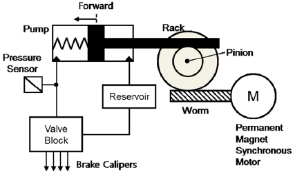
Fig. 1 shows the actuation part of the electro-hydraulic brake system, which consists of a reservoir, electric motor, reduction gear, piston pump, and valve module.
The piston-type hydraulic pump supplies brake oil to each of the brake calipers without any pressure pulsation. The brake pressure is controlled to follow the target pressure by measuring the pump pressure.
The valve block contains the hydraulic circuit comprising a number of solenoid valves, check valves, and orifices. By controlling the valve module together with the hydraulic pump, the electro-hydraulic brake system can provide active safety functionality to the vehicle such as the ABS(Anti-lock Brake System), TCS(Traction Control System), and ESC(Electronic Stability Control).
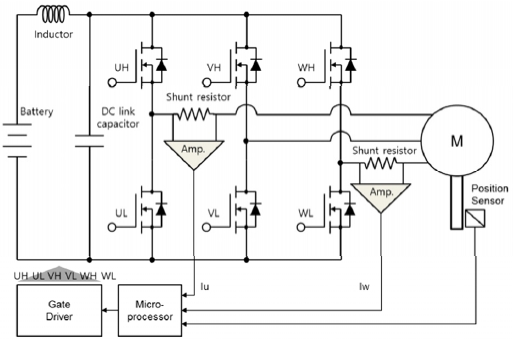
A surface mounted PMSM is adopted as the brake booster, which is characterized by its high power density and reduced torque ripple. Fig. 2 depicts the electric motor driver for the electro-hydraulic brake system. The 12 V battery supplies a stable DC power to the inverter through the LC smoothing circuit.
A low voltage metal oxide silicon field effect transistor(MOSFET) with minimum switching delay is used as a power device for the inverter and the phase currents of the motor are measured by placing the shunt resistors in series with the U and W phase of the motor. A giant magneto resistive position sensor with a built in fault detection circuit informs the microprocessor about the motor position and the fault status of the sensor itself.
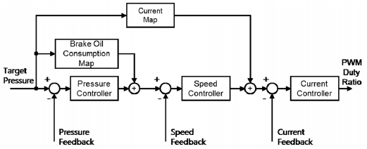
If the control system is in normal condition, the brake pressure is controlled by the electric motor as depicted in the block diagram in Fig. 3. Provided that the target brake pressure is given from the input part, the electric motor is controlled through a cascade of pressure control, speed control, and current control. The pressure, speed, and current controller perform the feedback control using the measured information from the pressure sensor, motor position sensor, and the current sensors, respectively.
Moreover, the feedforward control, utilizing the brake oil consumption characteristics of the caliper as well as the required motor current for the pressure build up is implemented to improve dynamic response and pressure control accuracy.
The conventional vector control algorithm for the three-phase PMSM calculates the required voltage to control the motor current, and the duty ratio for the power switch is determined from the SVPWM(Space Vector Pulse Width Modulation) method.
3. Observer-based Current Controller Design
If either of the current sensors is faulty, the current feedback signal in Fig. 3 is replaced by the observed current information. Jeong et al.5) proposed the current observer that estimates the motor current defined on the synchronous reference frame. The observer is designed based on the voltage equation of the motor expressed in the synchronous reference frame and the estimation error is compensated for by using a PI(Proportional and Integral) tracking controller if either of the current sensor signals is available.
Following the above approach, this paper presents the observer design making use of the projection matrices that remove the abnormal current signals defined on the stationary reference frame. In addition, the dead-time effect on the inverter is compensated for by referring to the direction of the estimated phase current.
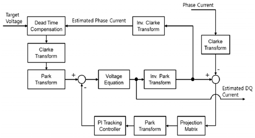
Fig. 4 depicts the block diagram of the current observer. The dead-time effect on the input voltage is compensated in accordance with equation (1) where the estimated phase current is used to determine the current direction.6) Subsequently, the input voltage is transformed to a quantity that is defined on the synchronous reference frame through Clarke and Park transformations given in equations (2) and (3), respectively.
| (1) |
| (2) |
| (3) |
The current is estimated from the voltage equation of the motor given in equations (4) and (5) where the error corrective voltage is subtracted from the voltage input.
| (4) |
| (5) |
The estimated current is defined on the synchronous reference frame and is related to the estimated phase current through the inverse Park and the inverse Clarke transformation given in equations (6) and (7).
| (6) |
| (7) |
If either of the current sensors is normal, the error correction voltage compensates for the current estimation error by using the sensor signal. The motor current defined on the stationary reference frame is related to the current measurement by the Clarke transformation given in equation (8) where the relation ib = -ia-ic is used in equation (2). If the column vectors and their orthogonal complements are defined as in equations (9) and (10), the relations hold that .
| (8) |
| (9) |
| (10) |
Based on the abovementioned vectors, the projection matrix Q that removes the faulty signals is derived in Table 1. The motor current defined on the stationary reference frame is projected in the direction of the current vector qa or qc depending on the fault condition.
Because of the transient behavior of the estimation error, it can be noted that the observer is activated even if the current sensor is normal, by defining the projection matrix as the identity matrix. The projected current estimation error is then transformed to the synchronous reference frame through the Park transformation as per equation (11).
| (11) |
Finally, the corrective voltage is obtained from the PI tracking controller as in equations (12) and (13).
| (12) |
| (13) |
Compared with the observer design presented in Jeong et al.,5) it is noted that the observer gain matrix is designed on the stationary reference frame by introducing the projection matrix, and the estimation accuracy is further improved by feeding back the estimated current to compensate for the dead-time effect.
4. Open-Loop Current and Speed Controller Design
The observer-based current controller presented in the previous section requires the exact position of the motor magnet, as the estimator is relying on the voltage equation defined on the synchronous reference frame. Therefore, another control strategy is necessary if fault in the position sensor as well as the current sensors occur simultaneously.
In this paper, an open-loop current controller is designed based on the assumption that the reference frame is aligned sufficiently well with the synchronous reference frame. At the same time, a brake pressure controller that is based on an open-loop speed controller is also proposed that guarantees the above premise.
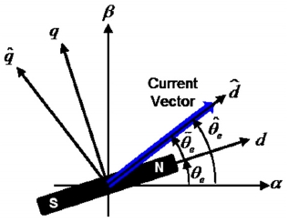
Assuming that the reference frame formed by the and axes is leading the synchronous reference frame by an electric angle and that is negligible as depicted in Fig. 5, the voltage equation on these axes can be written as in equations (14) and (15).
| (14) |
| (15) |
If the angle is limited to a small value and the motor speed ωe is controlled to exactly track the target speed , the open-loop current controller can be derived as in equations (16) and (17).
| (16) |
| (17) |
where it is assumed further that is set to zero and accurate value of the motor parameter is available.
The assumptions made above can be satisfied by controlling the axis current to a sufficiently larger value than that required by the conventional MTPA(Maximum Torque Per Ampere) method. In this case, only the q axis component of the current vector, which amounts to , contributes to the motor torque generation.
Putting together the above discussion and equations, the equation of motion for the electric motor can be described by equations (18)-(21). The motor torque described by equations (19)-(21) shows that it is nonlinear with respect to the deviation between the target and actual angle of the motor. The torque is proportional to the deviation angle if the deviation is sufficiently small, but the motor torque is decreased if the deviation angle exceeds 90°, which may lead to system instability.
The motor torque τc is also proportional to the motor current. Thus, the deviation angle can be reduced by increasing the motor current provided that the load torque remains constant. This means that the system can be regarded as a nonlinear spring-mass-damper system where the control input is pulling the motor through a nonlinear spring with the stiffness being proportional to the motor current.
| (18) |
| (19) |
| (20) |
| (21) |
The basic idea of the proposed algorithm is to control the magnitude of the current vector according to the load torque, such that the deviation angle is maintained within a sufficiently small region while the motor speed is controlled by rotating the current vector according to the target speed.
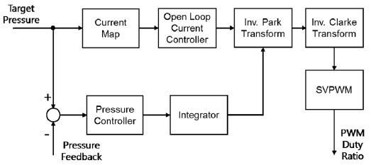
Fig. 6 shows the block diagram of the proposed brake pressure controller. The current map determines the axis target current according to the target brake pressure. In addition, the target speed of the motor is determined from the pressure controller output. A proportional controller is used to compensate for the brake pressure error as per equations (23) and (24) where the pressure sensitivity dP/dV is determined from the brake oil consumption characteristics of the brake caliper. The proportional gain for the controller is designed to make the closed loop system behave like a first order system with time constant τs as can be confirmed by the equations with the assumption being .
| (22) |
| (23) |
| (24) |
The rate of change of target speed is limited by the rotational inertia of the system to prevent the out of synchronization of the motor. In addition, the maximum target speed is also limited below the base speed of the motor because precise flux weakening control is not possible without the exact information of motor magnet position. Finally, the target position of the motor is derived by integrating the target speed and it determines the direction of the reference current vector.
The control algorithm proposed in this paper is neither relying on the position information of the motor magnet nor on the current sensor feedback. In addition, the control algorithm can be applied to all types of the PMSM although this paper is dealing with the surface mounted type. For interior permanent magnet synchronous motor with the different inductances along the reference frame axis, it only needs relevant modifications to the voltage equation (4), (5), (14) and (15). Compared with the conventional position sensor-less algorithms, which are based on the high frequency voltage injection technique,7,8) or the back electromotive force estimation method,9,10) the proposed algorithm can be applied to a wide speed range and is simple to be implemented.
On the other hand, it should be noted that the proposed controller provides a limited braking performance due to the limit on the motor speed and the excessive consumption of current. Furthermore, hunting in the motor due to lack of system damping, limits the application of the proposed control method. This is especially so, if the driving frequency of the motor speed is near the system resonant frequency defined by , where the hunting might lead to system instability.
Nevertheless, test results in the subsequent chapter show that the performance of proposed control algorithm is fairly good enough as a fault tolerant controller of the electrohydraulic brake system.
5. Experimental Results
For the experimental setup, the prototype electro-hydraulic brake system with 32-bit microprocessor was used. Four brake disks are mounted on the test bench and the brake calipers are connected to the system through the pipe where the pressure sensor is installed to measure the braking pressure. The proposed control algorithm was implemented as embedded software of the microprocessor. The data measurement, controller parameter tuning and the target braking pressure setting was performed using a commercial ECU development tool.
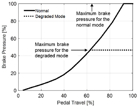
Fig. 7 describes the overall control characteristic of the proposed fault tolerant control in this paper. When a fault is detected in the position or current sensor, the maximum target pressure in the degraded mode is limited to below one half of that in the normal mode. Despite the limited maximum brake pressure, the brake booster remains available under maximum target pressure such that the mode enables the vehicle to limp home more safely.
5.1 Current Sensor Fault Cases
The test results plotted in Figs. 8-11 show the brake pressure control performance when the current observer feedback control is applied. For each figure, the figure on the left depicts the case where only one of the current sensor (phase-a) is faulty and the figure on the right shows the case when both the sensors are faulty.
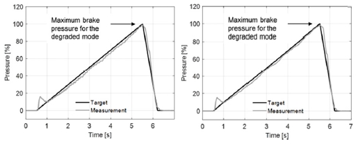
Ramp response of the brake pressure in case of (Left) phase-a sensor fault, (Right) phase-a and phase-c sensor fault
The ramp response of the brake pressure shows the accuracy of the current observer over the load conditions. Fig. 9 shows that the estimation error is reduced further when only one of the current sensors is faulty, as the motor current estimation in direction that the normal sensor signal affects is corrected by the PI tracking controller. As a result, the electro-hydraulic brake system maintains a good pressure control performance even if either of the current sensors is faulty.
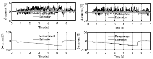
Motor current estimation in case of (Left) phase-a sensor fault, (Right) phase-a and phase-c sensor fault
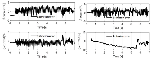
Estimation error of the motor current in case of (Left) phase-a sensor fault, (Right) phase-a and phase-c sensor fault
5.2 Simultaneous Fault Case of the Current Sensor and Position Sensor
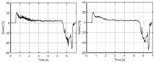
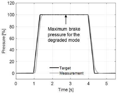
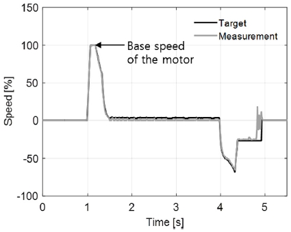
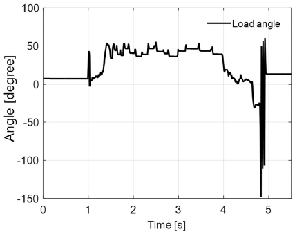
Figs. 12-16 show the test results of the proposed open-loop controller when the brake pedal is pressed and released quickly in the simultaneous fault situation of the current sensor and position sensor. This test case is regarded as the worst case in terms of the possible instability incurred by the out of synchronization of the motor.
Fig. 13 shows the current control performance. Although the current is roughly following the reference, it is shown that the speed is tracking the target such that the brake pressure reaches its maximum value within 0.4 [s]. The fluctuation in the speed and current observed at 4.9 [s] is due to the out of synchronization caused by trying to retract the pump piston at the end of the stroke position.
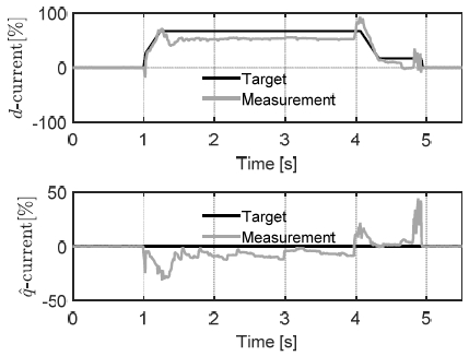
Control performance of the motor current in case of simultaneous fault of current and position sensors
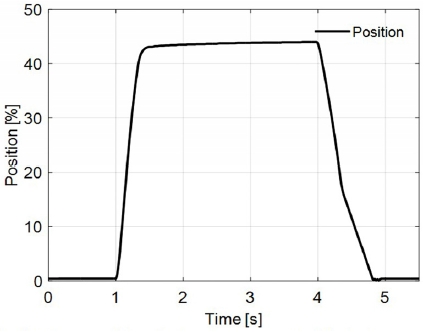
Motor position (piston displacement of the brake pump) in case of simultaneous fault of current and position sensors
Fig. 16 shows the load angle between the motor magnet and the current vector. This is meaningful for the time interval 1 [s]~5 [s] when the current vector is nonzero. It is shown that the load angle is maintained within 50 [deg] guaranteeing that the control system is safe from the out of synchronization of the motor.
6. Conclusion
This paper presents the fault tolerant a control algorithm for the electro-hydraulic brake system capable of coping with position and current sensor faults of a PMSM driven brake booster.
To keep the motor drive tolerant against sensor faults, an observer-based current feedback controller and a pressure control algorithm, which are independent of position and current sensor signals, are proposed.
If either of current sensors is faulty while the position sensor is still normal, the current defined on the synchronous reference frame is estimated. The current observer estimates the current based on the voltage equation of the motor. The projection matrix filtering out the faulty signals and the dead-time compensation are also discussed to improve the accuracy of the observed signals. It is shown that the observer estimates the current within 10% error and the observer-based feedback controller provides an almost equivalent dynamic performance compared with a normal measurement feedback control.
When both the position sensor and current sensors are faulty, the motor current is controlled by the open-loop algorithm, where a dedicated position sensor-less controller is also designed. The position sensor-less controller is also based on the open-loop speed control method and guarantees the alignment of the current vector with the motor magnet within the prescribed region. Despite the limitation on the braking performance, it is claimed that the algorithm enables the vehicle to limp home more safely.
The overall performance and stability of the developed control algorithms are experimentally investigated through different tests. The test result shows that about 50 % of the maximum brake pressure can still be generated even if the current and position sensors are all faulty. Therefore, it is concluded that the algorithm can be utilized as an effective means of degraded control of the electro-hydraulic brake system when the motor drive undergoes any sensor fault.
Nomenclature
| vkn : | pole voltage of phase-k |
| Td : | dead-time of the inverter |
| Tc : | PWM switching period |
| vdc : | DC link voltage |
| vα, vβ : | voltage defined on the stationary reference frame |
| vd, vq : | voltage defined on the synchronous reference frame |
| id, iq : | current defined on the synchronous reference frame |
| , : | current estimates |
| , : | current reference |
| , : | error corrective voltage |
| , : | proportional and integral gain for the error tracking controller |
| : | electrical angle of the motor |
| ωe : | electrical angular speed of the motor |
| L : | phase inductance |
| R : | phase resistance |
| λf : | back electromotive force coefficient |
| J : | rotational inertia of the motor |
| θm : | mechanical angle of the motor |
| τl : | load torque |
| τc : | motor torque |
| I : | magnitude of current vector |
| : | angle of current vector |
| Np : | number of pole |
| P : | brake pressure |
| P* : | reference brake pressure |
| V : | volume of brake fluid |
| Ap : | piston area |
| GR : | gear ratio |
| kpr : | proportional gain for the pressure controller |
References
- S. Hano and M. Hakiai, “New Challenges for Brake and Modulation Systems in Hybrid Electric Vehicles (HEVs) and Electric Vehicles (EVs),” SAE 2011-39-7210, 2011.
-
C. von Albrichsfeld and J. Karner, “Brake System for Hybrid and Electric Vehicles,” SAE 2009-01-1217, 2009.
[https://doi.org/10.4271/2009-01-1217]

- K. Choi, S. Cha, H. Lee and G. Kim, “Development of IDB Simulation Model,” KSAE Annual Conference Proceedings, pp.466-467, 2018.
-
J. Lee and S. Choi, “Braking Control of Electromechanical Brake Vehicle for Improving Ride Comfort,” KSAE Spring Conference Proceedings, pp.547-552, 2018.
[https://doi.org/10.1051/matecconf/201816602002]

-
Y. S. Jeong, S. -K. Sul, S. E. Schulz and N. R. Patel, “Fault Detection and Fault-tolerant Control of Interior Permanent-Magnet Motor Drive System for Electric Vehicle,” IEEE Transactions on Industry Applications, Vol.41, No.1, pp.46- 51, 2005.
[https://doi.org/10.1109/TIA.2004.840947]

- S. -K. Sul, Control of Electric Machine Drive Systems, John Wiley & Sons, New Jersey, 2011.
-
J. -I. Ha, “Analysis of Inherent Magnetic Position Sensors in Symmetric AC Machines for Zero or Low Speed Sensorless Drives,” IEEE Transaction on Magnetics, Vol.44, No.12, pp.4689-4696, 2008.
[https://doi.org/10.1109/TMAG.2008.2003479]

-
S. Kim, J. -I. Ha and S. -K. Sul, “PWM Switching Frequency Signal Injection Sensorless Method in IPMSM,” IEEE Transaction on Industry Application, Vol.48, No.5, pp.1576-1587, 2012.
[https://doi.org/10.1109/TIA.2012.2210175]

-
K. -W. Lee and J. -I. Ha, “Evaluation of Back-EMF Estimators for Sensorless Control of Permanent Magnet Synchronous Motors,” Journal of Power Electronics, Vol.12, No.4, pp.604-614, 2012.
[https://doi.org/10.6113/JPE.2012.12.4.604]

-
J. -K. Seok, J. -K. Lee and D. -C. Lee, “Sensorless Speed Control of Nonsalient Permanent-Magnet Synchronous Motor Using Rotor-Position-Tracking PI Controller,” IEEE Transactions on Industrial Electronics, Vol.53, No.2, pp.399-405, 2006.
[https://doi.org/10.1109/TIE.2006.870728]

