최적화 기법을 이용한 대형 상용차량 최악 주행 안정성 평가
Copyright Ⓒ 2019 KSAE / 166-07
This is an Open-Access article distributed under the terms of the Creative Commons Attribution Non-Commercial License(http://creativecommons.org/licenses/by-nc/3.0) which permits unrestricted non-commercial use, distribution, and reproduction in any medium provided the original work is properly cited.
Abstract
Serious accidents may occur in the case of heavy duty commercial vehicles, such as buses and trucks. As a result, electronic stability control(ESC) systems are increasingly being installed in order to improve the stability of vehicles. NHTSA has proposed a standard test method to evaluate the stability of a vehicle equipped with these systems; however, the evaluation in the worst-case driving scenario is determined to be insufficient. In this study, the worst-case stability evaluation method is derived by using a pattern search optimization method based on NHTSA’s step steering input test(J-turn) and sine-with-dwell test. According to the simulation result, the stability of the vehicle can be evaluated better through the worst-case driving condition test as compared to the NHTSA test method that was used for vehicle stability evaluation.
Keywords:
Worst case scenario generation, Step steering test, Sine-with-dwell test, Pattern search, Heavy duty commercial vehicles, ESC(Electronic stability control)키워드:
최악조건 생성, 스텝 조향 시험, 드웰 사인 시험, 패턴 검색, 대형 상용차량, 전자 안정성 제어1. 서 론
버스, 트럭 등 대형 상용차량의 경우 사고 발생 시 대형 사고로 이어져 인적, 물적 피해가 매우 크다. 이에 따라 이들 대형 상용차량에는 차량 주행 제어 시스템의 장착이 늘어나고 있다. 차량 주행 제어 시스템은 여러 가지 시험 시나리오를 토대로 성능을 예측하고 있지만, 정해진 시험 조건 이상의 최악 조건(Worst case)을 평가하는 데는 한계가 있다.1) 또한 대형 상용차량의 경우 화물 적재 시 질량 중심의 위치가 높아지기 때문에 선회 또는 급차선 변경 시 원심력에 의해 차량의 전복이 쉽게 발생할 가능성이 높기 때문에 차량 자세 제어를 통한 주행 안정성 확보가 필수적이다. 그러나 실제 주행 시 발생할 수 있는 대형 상용차량의 다양한 최악 주행 상황을 예측하여 시스템을 개발하는 것은 어려운 일이다.2) 이에 따라 가능한 최악 주행 상황을 수치적으로 파악 할 수 있는 시뮬레이션 방법을 개발하여 차량 주행 제어 시스템 개발에 적용하는 것은 좀 더 신뢰성 있는 시스템 개발이 가능하다고 할 수 있다.3)
본 연구에서는 대형 상용차량의 전자 안정성 제어(ESC, Electronic Stability Control) 시스템 개발을 위하여 4.5ton 트럭을 대상으로 기존 주행 시험 평가 방법으로 제시되고 있는 NHTSA4) 스텝 조향 입력 시험(Step steering test, J-turn), Sine-with-dwell 시험 등을 기본으로 하여 최악 주행 상황 시험 방법을 도출하였으며 시뮬레이션을 수행하여 기존 시험 방법과 도출된 최악 주행 상황 시험 방법을 비교 분석하였다.
2. 최악 상황 시나리오 도출
2.1 최적화 알고리즘
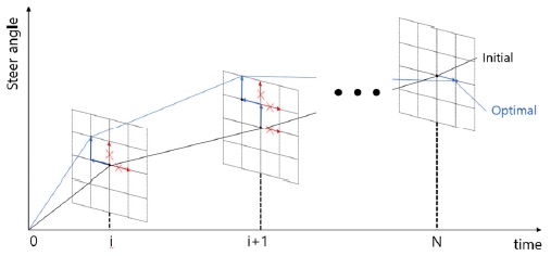
최적화 알고리즘으로 사용한 패턴 검색 방법(Pattern search)은 현재 점에서 목적함수를 최소화 시키는 다음 점을 찾기 위해 x, -x, y, -y 방향으로 1메쉬 만큼 이동하여 기존 값과 비교하여 최소값이 존재하면 그 점으로 이동하는 방법이다.
Fig. 1은 각 시간 간격에서의 패턴 검색 방법을 사용하여 최소값을 찾는 개념도를 나타낸 것이다. 그림에서 보는 바와 같이 각 시간(0, …, i, i+1, …, N)에서 기존 조향각을 초기값(NHTSA 스텝 조향 입력 시험(Step steering test, J-turn), Sine-with-dwell 시험)으로 설정하고 패턴 검색 방법을 이용하여 최소값을 찾은 후 다음 단계에서 도출된 최적점을 차례로 연결한다.
2.2 최악상황 정의
운전자의 방향 전환 의도는 조향 입력으로 나타나며 차량은 조향입력에 의해 요 운동(Yaw motion)을 하게 된다. 차량의 횡방향 안정성은 횡슬립각(Side slip angle)으로 표현된다. 최악의 상황은 운전자 의도에 따른 조향입력에 의한 목표 요율(Desired yaw rate)로부터 실제 요율(Actual yaw rate)이 최대한 이탈되면서 횡슬립각(Side slip angle)이 최대한 커질 때가 횡방향 안정성이 최악의 상황이라고 할 수 있다.5) 최적화 알고리즘을 사용하여 목표 요율(Desired yaw rate)과 실제 요율(Actual yaw rate)의 차이의 합과 차체 횡슬립각의 합을 식 (1)로 표현하였다.
| (1) |
여기에서
γ : 실제 요율(actual yaw rate)
γd : 목표 요율(desired yaw rate)
β : 횡슬립 각(side slip angle)
식 (1)의 각 항을 제곱하여 값을 양수가 되도록 사용하고 목적함수인 식 (2)를 다음과 같이 정의하였다.6) 식 (2)에서 C1은 상수이므로 식 (1)이 커질수록 목적함수 L(δ)는 작아지게 된다. 따라서 최적화 알고리즘을 통하여 목적함수 L(δ)를 가장 작게 할 수 있는 값을 구하게 되면 운전자의 의도하는 조향 입력은 목표 요율과 실제요율의 차이가 크고 횡슬립각의 값이 커진다. 따라서 차량의 주행 상황을 최악으로 만드는 조향 입력이라고 할 수 있다.
| (2) |
여기에서
δ(ti) : 조향입력(steering input)
γ(ti) : 요율(yaw rate)
γdesire (ti) : 목표 요율(desired yaw rate)
β(ti) : 횡슬립 각(side slip angle)
ti : 시간(time)
C1 : 상수(constant consideration sensitivity)
을 각각 나타낸다.
2.3 최악의 상황 시나리오 도출 흐름도
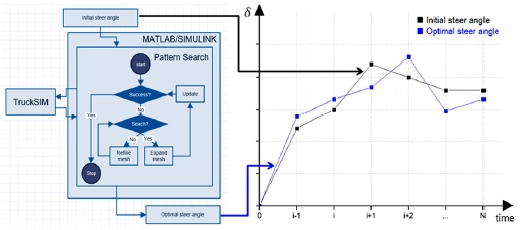
본 연구에서 사용한 최악 주행 상황 도출 방법의 전체적인 개념도를 Fig. 2에 도시하였다.7,8)
Fig. 2의 오른쪽 그림에서 보는 바와 같이 기존 주행 시나리오의 조향각을 시간 간격으로 나누어 각 시간에서 최적화 알고리즘9-11)을 통하여 구해진 최악 주행 조향각을 순차적으로 연결하여 최악 주행 시나리오를 도출한다. 초기 조향각은 NHTSA 스텝 조향 입력 시험(Step steering test, J-turn), sine-with-dwell 시험의 두 가지 시나리오를 참고한다. 초기 조향각으로 최적화 알고리즘을 이용하여 도출한 최악 주행 상황 생성 조향각을 TruckSim S/W에 입력하여 최악의 상황을 도출하는 주행 시뮬레이션을 실시하였다. Worst case인 주행시나리오의 경우는 최적화 알고리즘을 통하여 얻은 Optimal steer angle의 각 시간 스텝별로 도출되면 x축을 시간 y축을 Optimal steer angle로 하여 그래프로 생성한다.
3. NHTSA 평가 방법 기반 최악 주행 시나리오 도출
4.5 ton 트럭을 대상으로 NHTSA 스텝 조향 입력 시험(Step steering test, J-turn)과 Sine-with-dwell 시험을 기준으로 최악 주행 상황 시험법을 도출하였다. TruckSim을 이용하여 4.5 ton 트럭을 모델링하였으며 MATLAB/Simulink18) 최적화 알고리즘과 연동하여 시뮬레이션을 수행하였다.17)
3.1 스텝 조향 입력(J-turn) 시험
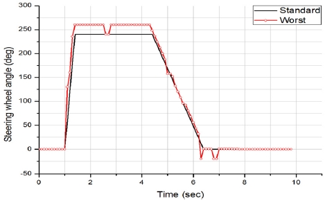
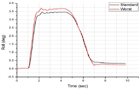
식 (2)를 이용하여 NHTSA 스텝 조향 입력 시험16)에 기반하여 최악 주행 상황 시험법을 도출하였다. 차량 속도 80 km/h로 주행 시 도출한 조향 입력을 Fig. 3에 나타내었다. 그림에서 보는 바와 같이 조향 입력은 NHTSA 스텝 조향 입력 시험에 비하여 약간 증가함을 알 수 있다. Figs. 4~6에 롤 각, 요 율, 바퀴 중심 위치에 대한 시뮬레이션 결과를 도시하였으며 Table 1에 결과를 정리하였다.
Table 1에서 보는 바와 같이 차량의 롤 각, 요 율, 바퀴 들림이 전체적으로 증가하였다. 증가량은 각각 6.3 %, 6.2 %, 0.2 %이며 최악 상황 조향 입력이 기존 조향 입력에 비해 차량 응답을 크게 발생시킬 수 있음을 알 수 있다.
이에 따라 기존에 차량 주행 안정성 평가를 위해 사용되었던 NHTSA 스텝 조향 입력 시험에 비하여 좀 더 가혹한 조건의 시험을 통하여 차량 주행 안정성평가가 가능할 것이다.
3.2 Sine-with-dwell 시험
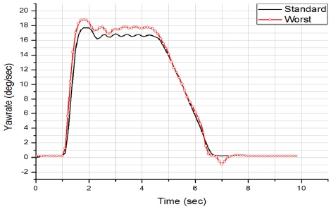
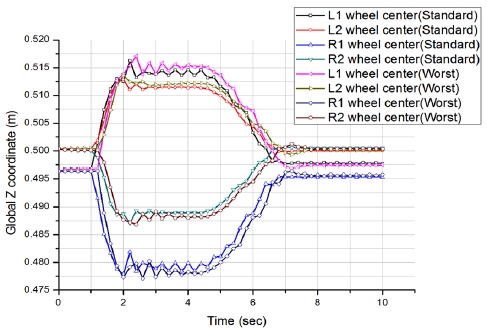
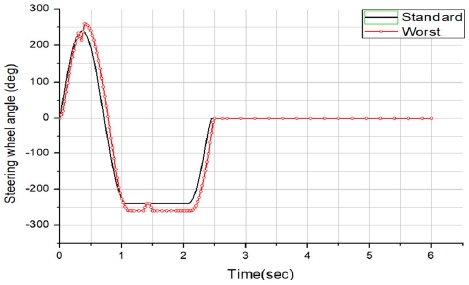
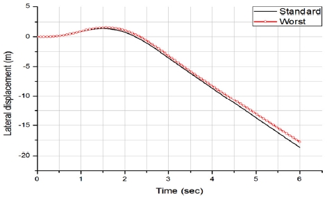
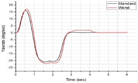
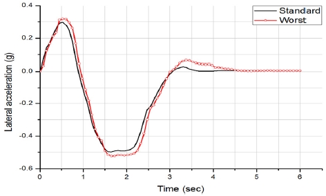
Sine-with-dwell 시험은 0.5 Hz의 사인 조향에 3/4 Cycle에서 1초 정지시간(Dwell time)을 갖는 신호파형이다.12-14) 차량의 전복 성능 평가 등 주행 안정성을 평가할 수 있는 시험 방법으로 알려져 있다. 식 (2)를 이용하여 NHTSA sine-with-dwell 시험에 기반하여 최악 주행 상황 시험법을 도출하였다. 차량 속도 72 km/h±1.6 으로 주행 시 도출한 최악 주행 상황 조향 입력을 Fig. 7에 도시하였으며 두 가지 경우에 대한 시뮬레이션 결과를 Figs. 8~10에 도시하였다.
NHTSA sine-with-dwell 시험을 통하여 차량의 주행 안정성을 평가하는 경우 횡가속도 비(Lateral acceleration ratio), 요율 비(Yaw rate ratio), 횡방향 변위(Lateral displacement) 등의 항목을 평가한다. 이들 항목의 평가기준은 식 (3) ~ (5)로 이 기준을 만족해야 한다.15)
횡가속도 비(lateral acceleration ratio) :
| (3) |
여기에서
At : 횡가속도(lateral acceleration)
Amax : 최대 횡가속도
t0 : 조향 입력 완료 시간
을 각각 나타낸다.
요율비(yaw rate ratio) :
| (4) |
여기에서
: 요율(yaw rate)
: 첫 peak 요율
t0 : 조향 입력 완료 시간
을 각각 나타낸다.
횡방향 변위(lateral displacement) :
| (5) |
여기에서
AgC.G : 횡가속도
t0 : 조향 입력 완료 시간
을 각각 나타낸다.
Fig. 7에서 보는 바와 같이 최악 주행 상황 조향 입력을 보면 초기 조향각이 최대가 되는 0.42초와 1.3초 ~ 2.3초 사이의 정지(Dwell)부분에서 가장 큰 변화를 보이고 있으며 요율(Fig. 9)과 횡가속도(Fig. 10) 응답에서도 크게 변화함을 알 수 있다.
Table 2~4에서 보는 바와 같이 NHTSA sine-with- dwell 시험에 비하여 최악 주행 상황 조향 입력 시뮬레이션 결과 차량의 롤 각, 요각속도, 횡가속도가 증가하였다.

Lateral acceleration ratio between standard sine-with-dwell and worst case scenario simulation results
Table 4에서 보는 바와 같이 횡방향 변위가 NHTSA sine-with-dwell 시험 시 1.39 m로 평가 기준인 1.52 m 내로 들어오지만 최악 주행 조향 입력 시는 1.57 m로 기준 값을 초과하여 판정 조건을 만족시키지 못한 것으로 나타났다. 또한 Table 3에서 보는 바와 같이 요율 비가 두 방법 모두 평가 기준을 만족하였지만 조향 완료 후 1.00초 지점에서 요율 비가 1.71에서 7.70으로 증가하여 NHTSA 시험 방법보다 약 3.4배 가혹했으며 1.75초 지점에서는 1.00에서 8.53으로 증가하여 약 7.5배 더 가혹한 시험으로 나타나 기존 NHTSA 시험법에 비해 훨씬 가혹한 시험을 통해 시스템을 평가할 수 있음을 알 수 있다.
4. 결 론
버스, 트럭 등 대형 상용차량의 경우 사고가 발생하면 대형사고로 이어지기 때문에 차량의 주행 안정성 향상을 위해 차량 안정성 제어(ESC, Electronic Stability Control) 시스템 등의 전자제어시스템 장착이 증가하고 있다.
- 1) NHTSA에서 제시하고 있는 스텝 조향 입력 시험(Step steering test, J-turn), Sine-with- dwell 시험 등 2가지 조향 입력을 기반으로 패턴 검색(Pattern search) 최적화 기법을 사용하여 최악 주행 상황 조향 입력을 도출하였으며 차량 시뮬레이션을 통해 주행안정성을 비교 분석하였다.스텝 조향 입력 시험(J-turn)의 경우 도출한 최악 주행 상황 조향 입력 결과 NHTSA 시험 방법에 비하여 차량의 롤 각은 6.3 %, 요 율은 6.2 %, 바퀴 들림은 0.2 % 증가하였다.Sine-with-dwell 시험의 경우 도출한 최악 주행 상황 입력 시뮬레이션 결과 횡방향 변위와 요율 비(Yaw rate ratio), 횡가속도 비(Lateral acceleration ratio)가 각각 12 %, 752 %, 272 % 증가하여 Understeer 및 Oversteer 측면에서 훨씬 가혹한 시험 결과를 얻었다.
- 2) 운전자의 조향 입력만으로 차량의 거동을 확인하고 TruckSIM과 MATLAB/Simulink 환경의 SILS(Software-in-the-loop)를 사용하여 제한적인 시뮬레이션을 진행하여 최악의 상황을 도출하였다.
- 3) 향후 UCC(Unified Chassis Control)를 활용하여 HILS(Hardware-in-the-loop)를 결합하여 얻은 결과와 자동 조향 장치를 사용한 실차 시험의 결과를 비교 분석할 필요가 있다. 신뢰성 있는 최적화 알고리즘에 대한 연구와 Worst 상황을 발생시키는 외란을 고려한 Malfunction 상황(Loss of assist and Unintended steer)조건에 대한 부분도 연구를 통하여 개발되어야 할 것이다. 다양한 시험법과 연구 개발될 시스템의 평가 방법으로 고려할 필요가 있다.
Acknowledgments
본 연구는 한국산업기술평가관리원에서 주관하는 자동차산업핵심기술개발사업“안전 규제 대응 및 사고 방지를 위한 상용차용 공압식 차량 안정성 제어 시스템 개발” 과제의 성과물로써 관계자 여러분께 감사드립니다(과제번호 : 10070168).
References
-
W. Ma, and H. Peng, “A Worst-Case Evaluation Method for Dynamic Systems”, ASME Journal of Dynamic Systems, Measurement and Control, 121(2), p191-199, (1999).
[https://doi.org/10.1115/1.2802454]

- A. Y. Ungoren, and H. Peng, “Evaluation of Vehicle Dynamic Control for Rollover Prevention”, Int. J. Automotive Technology, 5(2), p115-122, (2004).
-
T. J. Wielenga, “A Method for Reducing On Road Rollovers–Anti-rollover Braking”, SAE 1999-01-0123, (1999).
[https://doi.org/10.4271/1999-01-0123]

- National Highway Traffic Safety Administration, http://www.nhtsa.gov (2018).
- S. J. Yim, Y. J. Park, and Y. S. Park, “Worst-Case Evaluation for Vehicle Dynamics Controller Systems”, KSAE Fall Conference Proceedings, p656-661, (2004).
- J. Y. Kim, D. H. Jung, C. H. Jeong, and H. J. Choi, “Wosrt-case Development and Evaluation for Vehicle Dynamics Controller in UCC HILS”, Transactions of KSAE, 19(6), p30-36, (2011).
- D. Y. Jung, D. H. Jung, K. H. Moon, C. H. Jeong, K. H. Noh, and H. J. Choi, “Worst Case Scenario Generation on Vehicle Dynamic Stability and its Application”, Transactions of KSAE, 16(6), p1-9, (2008).
-
S. Jayasuriya, “On the Determination of the Worst Allowable Persistent Bounded Disturbance for a System with Constraints”, ASME Journal of Dynamic Systems, Measurement and Control, 117(2), p126-133, (1995).
[https://doi.org/10.1115/1.2835172]

- M. Athans, and P. L. Falb, Optimal Control, McGraw-Hill, New York, (1966).
- S. K. Agrawal, and B. C. Fabien, Optimization of Dynamic Systems, Kluwer Academic Publishers, Netherlands, (1999).
- J. S. Arora, Introduction to Optimum Design, McGraw-Hill, New York, (1989).
- M. C. Jung, and J. H. Jang, “A Study on Vehicle Spinout Related Test and Metrics”, KSAE Fall Conference Proceedings, p993-998, (2006).
- S. S. Kim, J. H. Lim, Y. D. Jeon, and B. D. Kang, “A Study on the Performance Test method for ESC of Heavy Vehicle”, KSAE Annual Conference Proceedings, p2188-2194, (2013).
- S. H. Chung, S. J. Kwon, S. S. Kim, and B. H. Lee, “A Study on Function and Control of the Commercial Vehicle Electronic Stability Program System”, KSAE Annual Conference Proceedings, p550-555, (2014).
- M. C. Jung, and J. H. Jang, “Sine with Dwell Test Final Rule and Actual Application Test Results”, KSAE Fall Conference Proceedings, p786-791, (2007).
- J. M. Yi, J. H. Park, and D. H. Lee, “A Study on Mechanism of Vehicle Response and Analysis of Rolling Motion Using Step Input Test”, KSAE04-L0054, p26-32, (2004).
- M. G. Hong, and G. J. Choi, “Evaluation of Worst-case Scenarios for Driving Stability of Commercial Vehicle”, KSAE Fall Conference Proceedings, p408-409, (2017).
- MATLAB/SIMULINK User’s Manual, http://www.mathwork.com (2018).

