Improving the Cooling Efficiency for the Molding of a Complex Automotive Plastic Part by 3D Printing Technology
Copyright Ⓒ 2017 KSAE
Abstract
This work presents the design of an injection mold cooling system for the production of a plastic automotive door module. The traditional cooling channel with straight-line drilling could not cool the mold effectively, and the cycle time was longer than expected due to the varying thickness of the parts. Therefore, a specially designed cooling system has been proposed. Instead of a straight line, the cooling channels were in spiral form. This shape could only be fabricated via selective laser melting 3D printing technology with metal powder. In order to save the manufacturing cost and maximize the efficiency of the proposed cooling system, the mold was designed with special inserts and optimum geometrical parameters. The design process was done by using a combination of the analytical and numerical simulation methods. In addition, the real mold was produced and tested in order to prove the efficiency of the new cooling system. The research result showed that the cooling time was reduced by approximately 23 %, as compared to the traditional cooling system. This is a significant practical contribution to the injection molding technology.
Keywords:
Injection molding, Conformal cooling channels, Cooling efficiency, Design optimization1. Introduction
Mold cooling process accounts for more than two-thirds of the total cycle time in the production of injection molded thermoplastic parts. An efficient cooling circuit design reduces the cooling time, and in turn, increases overall productivity of the molding process. Moreover, uniform cooling improves part’s quality by reducing residual stresses and maintaining dimensional accuracy and stability. Therefore, the system of cooling channels plays a crucial role in the injection mold. Simple and traditional cooling channels cannot result in an even and effective cooling function when the molded part is complex. Recently, the advancement in additive manufacturing technology has introduced to mold making technology. Prototyping technologies with metal powder such as selective laser sintering can make the mold with conformal cooling channels. It was said that this cooling channels not only ensure the high quality of the product but also increase the productivity of injection molding.
The application of conformal cooling channels made by solid freeform fabrication is becoming popular recently. This type of cooling channels system is recognized as one of the best solutions in reducing cycle time, differential shrinkage, and warpage defects on molded parts.1) Conformal cooling channel has drawn great attention to mold designer and plastic molding researcher. Ferreira and Mateus studied on rapid soft tooling with conformal cooling channels for plastic injection molding.2) Wang et al. introduced an approach to generate spiral channels for conformal cooling system3) and concluded that the cooling channels derived from spiral curves introduce nearly no reduction of the rate of coolant flow. In addition, the channels are able to achieve uniform mold cooling. In literature, there are four types of conformal cooling channels: spiral conformal cooling channels,3,4) zigzag-type conformal cooling channels,4) scaffold type conformal cooling channels, 5) and Voronoi diagram type.6) However, the answerer for the question that which the best one is depends the particular circumstance.
Although conformal cooling channels applied to injection mold is no longer new, the design and optimization of conformal cooling channels for special practical application is still a research problem. Various researches developed the optimal design for cooling channels that can increase the effectiveness of cooling system in moulds; however, the optimal design of the cooling channels in the mold has been restricted by the relatively simple cooling channel configurations.7-10)
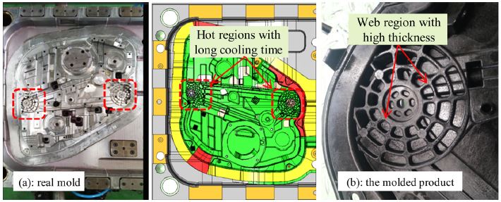
In this paper, a practical problem in injection molding industry for making an automotive plastic part is addressed. An injection mold was is to make a complicated car door module as shown in Fig. 1. Due to the functionality of the molded part, the web regions have high thickness. As the result, the temperature at these regions is too hot, and the cooling time is longest compared to other regions. As the result, the total cycle time is also long. In addition, the deformation of the molded part is also larger than expected. Therefore, it is necessary to reduce the cooling time for these regions. The target of the research is that the cooling time must be reduced at least 20 % at the first phase of the project. This number is significant contribution because the demand on injection molding technique is growth with the further development of the automobile design for cost reduction and environment-friendly use.11)
2. Development of the Effective Cooling Channels
2.1 Mathematical modelling of cooling process
The cooling process in injection molding is a complex heat transfer problem. The objective of mold cooling analysis is to find the temperature distribution in the molded part and mold cavity surface. Cyclea-veraged temperature approach is used for mold region and transition analysis is applied to the molded part.12-14)
The general heat conduction involving transition heat transfer problem is governed by the partial differential equation. The cycle-averaged temperature distribution can be represented by the steady-state Laplace heat conduction equation. When the heat balance is established, the heat flux transferred to the mold and the heat flux removed from the mold must be in equilibrium. The heat balance is expressed by equation:
| (1) |
where Qm and Qc are the heat flux from the melt, the heat flux exchange with coolant and environment respectively. The heat lost to the surrounded environment can be neglected.
Heat flux from the molten plastic into the coolant can be calculated as
| (2) |
where cp, TM, TE, im, r, s, x are the specific heat of plastic, melt temperature, latent heat, specific weight, molded part’s thickness, and pitch between cooling lines, respectively.
Heat flux from the mold exchanges with coolant in the time tc amounts to13):
| (3) |
where kp, d, kst, Se, TW, TC are thermal conductivity of polymer, cooling diameter, thermal conductivity of mold steel, shape factor, mold wall temperature, and coolant temperature, respectively.
The influence of the cooling channels position on heat conduction can be taken into account by applying shape factor15)Se.
| (4) |
Heat transfer coefficient of water is calculated by16)
| (5) |
where the Reynolds number
| (6) |
where d, u, and ν are diameter of cooling channel, coolant velocity, and kinetic viscosity of coolant(water), respectively.
The cooling time of a molded part in the form of plate is calculated as16)
| (7) |
| (8) |
From the formula (7), it can be seen that the cooling time only depends on the thermal properties of a plastic, part thickness, and process conditions. It does not directly depend on cooling channels configuration. However, cooling channels’ configuration influences the mold wall temperature, so it indirectly influences the cooling time.
By combining equations from (1) to (8), we can derive the following equation:
| (9) |
Mathematically, with preset TM, TE, TW, TC, predefined thermal properties of material, equation (9) presents the relation between cooling time tc and the variables related to cooling channels configuration including pitch x, depth y and diameter d. In reality, the mold wall temperature is established by the cooling channels configuration and predefined parameters TM, TE and thermal properties of material in equation (9). The value of TW, in turn, results in the cooling time calculated by the formula (7).
2.2 Design and optimize the cooling channel
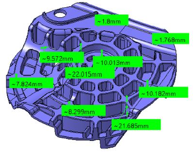
To proper design the cooling channel for the web regions as shown in Fig. 1, the analytical method was firstly employed based on the mathematical model presented in section 2.1. To identify the cooling time, the thickness at the web region must be estimated based on the volume of material of the projected area as depicted in Fig. 2.
| (10) |
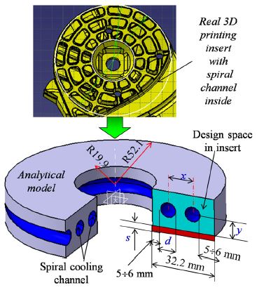
The predetermined parameters were chosen as shown in Table 1. The distance from the center of cooling channels to the mold surface is selected as 16 mm based on the guideline of injection mold design handbook. The design variables are the geometry of the cooling channel including diameter d and pitch x as shown in Fig. 3. Solving the equation (9) without constraints, we obtained multi solutions as shown in Table 2.
Due to the design space constraint as shown in Fig. 3,
32.2 -6×2 ≤ x + d ≤ 32.2 -5×2
⇔ 20.2 ≤ x + d ≤ 22.2 (mm)
and the practical relation between x and y
The optimal solution is selected as d = 7.0 and x = 13.9 mm.
2.3 Simulation of the cooling process
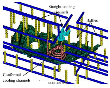
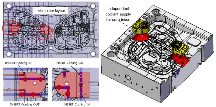
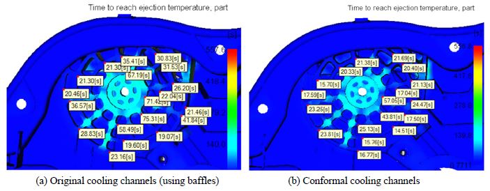
After analytical calculation, we used numerical simulation to verify the performance of the proposed design. The main cooling channel for the whole mold is retained. The main cooling system includes straight cooling lines and baffles. A new local conformal cooling channel is inserted to the mold core as shown in Fig. 4. The simulation results show that the time to reach ejection temperature for the web region of the molded part can be reduced approximately 31 %(see Fig. 5 and Table 3).
The comparison of average reduction of cooling time at a set of points between old and new cooling system
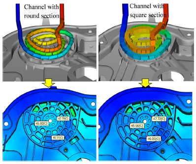
To determine which cooling channel is best, we also compare the different type of cross section of the cooling channel. Fig. 6 shows the comparison of two kind of cross sections: round and square shape. The Fig. 6 Comparison of channel with different section simulation results shows that there is not much different of part temperature between two kinds of cross section. However, the round cross section cooling channel is easier for manufacture than the square one and the crack caused by stress intensity in the round shape channel can be eliminated.
2.4 Layout and deployment of new cooling channel
The form and shape of inserts are considerable because of the manufacturability and constraints. We made two pockets in the existent mold and then added two insert made by 3D printing technology. The conformal cooling channels run inside the insert spirally. The coolant to the channels in the insert are supplied by an independent water pump so that we can easily control the flow rate or the temperature. The structure and assembly of insert in the mold with local conformal cooling are shown Fig. 7. To prevent coolant leakage, sealing by O-rings is required to apply between insert and the mold. The inserts are fixed to the mold by interference fit and two bolts.
2.5 Making the inserts by 3D printing technology
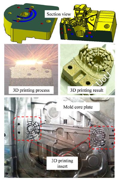
After design and simulation, the two inserts were fabricated by selective laser melting method on Metal-Sys 150 3D printer. The chemical composition of the material is given in Table 4. The surface of inserts are then machined the surface on CNC milling machine and assembled to the main mold as shown in Fig. 8. The mold is then ready to do the experiment.
3. Injection Testing and Result
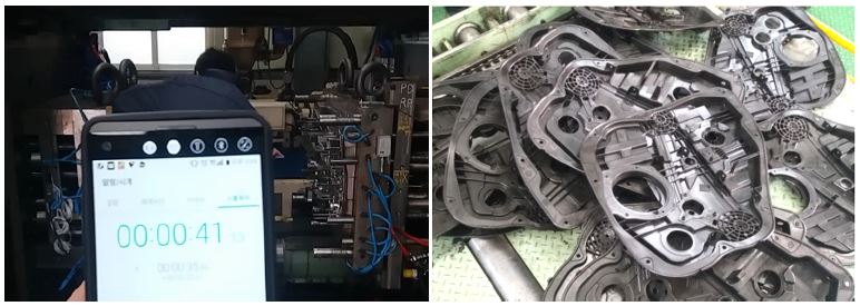
The testing process was done in order to verify the results. The molding process was carried out on an industrial injection molding machine Toshiba IS2500DF with 2500 tons of clamping force. The cycle time is measure by a stop watch. The experiment is shown in Fig. 9. Some of products were molded until the molding process reaches it steady stage. The results show that the real cooling time can be reduced from 39 sec to 30 sec(equivalent to 23 %) with the new cooling channel when using the coolant flow rate 2.25 litter/minute with the temperature of 16 Celsius degree. There is an error between simulation and real experiment due to the error of modelling, the simplification and the error material properties. In addition, the microstructure and physical properties of 3D printing material is different from those of the same metal made by metallurgy. It is clear that the cycle time is reduced significantly. When using the conformal cooling channels, the appearance of the molded part also looks better.
4. Conclusion and Future Works
This work studied on the way of improving the cooling efficiency of the molding process by using 3D printing technology and optimal design. We introduces local conformal cooling channels applied in a mediumsize injection mold that makes an automotive part. The combination of analytical method, simulation and experiment were used to obtain the reliable design in a scientific way. We analysed the current state and performance of the existent mold so that its drawback was drawn. The literature review method was also used to approach the state of the art and to decide the optimal solution. The spiral cooling channel was selected as the best choice of cooling performance. Selective laser melting method was used to fabricate the inserts. The real testing results show that the cooling time can be reduced to 23 %, a big number of improvement.
In practice, it is hard to obtain a large percentage of improvement for all case. This is special case due to the complication and the variation of the thickness of the molded part. The further target of this work is to continue to reduce the cooling time up to 50 %. This is a difficult task, and high thermal conductivity material will be used to make the inserts with conformal cooling channels so that they can take a large amount of heat inside the mold at a unit time. In addition, the cavity sensor system including temperature and pressure sensors is employed in order to obtain the process parameter inside to mold cavity. The signal will be used to control the molding process smartly. The quality of the molded part will be increased and consistent.
Acknowledgments
This work is supported by the Ministry of Trade, Industry & Energy(MOTIE, Korea) under Industrial Technology Innovation Program. No. 10062677. “For plastic injection molds with 50 % improved cooling efficiency, development of 3D printing equipment & mold steel powder manufacturing technology having 30 mm grade in diameter”.
References
-
Z. Shayfull, S. Sharif, A. M. Zain, M. F. Ghazali, and R. M. Saad, “Potential of Conformal Cooling Channels in Rapid Heat Cycle Molding: A Review”, Advances in Polymer Technology, Vol.33(Issue 1), (2014).
[https://doi.org/10.1002/adv.21381]

-
J. C. Ferreira, and A. Mateus, “Studies of Rapid Soft Tooling with Conformal Cooling Channels for Plastic Injection Moulding”, Journal of Materials Processing Technology, Vol.142(No.2), p508-516, (2003).
[https://doi.org/10.1016/s0924-0136(03)00650-2]

-
Y. Wang, K. -M. Yu, and C. C. L. Wang, “Spiral and Conformal Cooling in Plastic Injection Molding”, Computer-Aided Design, Vol.63, p1-11, (2015).
[https://doi.org/10.1016/j.cad.2014.11.012]

-
H. S. Park, and N. H. Pham, “Design of Conformal Cooling Channels for an Automotive Part”, Int. J. Automotive Technology, Vol.10(No.1), p87-93, (2009).
[https://doi.org/10.1007/s12239-009-0011-7]

-
K. M. Au, and K. M. Yu, “A Scaffolding Architecture for Conformal Cooling Design in Rapid Plastic Injection Moulding”, The International Journal of Advanced Manufacturing Technology, Vol.34(Issue 5), p496-515, (2007).
[https://doi.org/10.1007/s00170-006-0879-6]

-
Y. Wang, K.-M. Yu, C. C. L. Wang, and Y. Zhang, “Automatic Design of Conformal Cooling Circuits for Rapid Tooling”, Computer- Aided Design, Vol.43(No.8), p1001-1010, (2011).
[https://doi.org/10.1016/j.cad.2011.04.011]

-
S. A. Jahan, and H. El-Mounayri, “Optimal Conformal Cooling Channels in 3D Printed Dies for Plastic Injection Molding”, Procedia Manufacturing, Vol.5, p888-900, (2016).
[https://doi.org/10.1016/j.promfg.2016.08.076]

-
D. -G. Ahn, S. -H. Park, and H. -S. Kim, “Manufacture of an Injection mould with Rapid and Uniform Cooling Characteristics for the Fan Parts Using a DMT Process”, International Journal of Precision Engineering and Manufacturing, Vol.11(No.6), p915-924, (2010).
[https://doi.org/10.1007/s12541-010-0111-3]

- M. Khan, S. K. Afaq, N. U. Khan, and S. Ahmad, “Cycle Time Reduction in Injection Molding Process by Selection of Robust Cooling Channel Design”, ISRN Mechanical Engineering 2014, No.1, p1-8, (2014).
- L. E. Rännar, A. Glad, and C. G. Gustafson, “Efficient Cooling with Tool Inserts Manufactured by Electron Beam Melting”, Rapid Prototyping Journal, Vol.13(No.3), p128-135, (2007).
- D. J. Choi, and H. S. Park, “Optimization of Multi-component Injection Molding Process Based on Core-back System”, Transactions of the KSAE, Vol.17(No.2), p67-74, (2009).
-
Z. C. Lin, and M. H. Chou, “Design of the Cooling Channels in Nonrectangular Plastic Flat Injection Mold”, Journal of Manufacturing Systems, Vol.21(No.3), p167-186, (2002).
[https://doi.org/10.1016/s0278-6125(02)80160-1]

-
S. J. Park, and T. H. Kwon, “Optimal Cooling System Design for the Injection Molding Process”, Polymer Engineering & Science, Vol.38(No.9), p1450-1462, (1998).
[https://doi.org/10.1002/pen.10316]

- L. E. Rännar, On Optimization of Injection Molding Cooling, Ph. D. Dissertation, Norwegian University of Science and Technology, Trondheim, (2008).
- J. P. Holman, Heat Transfer, 9th Edn., McGraw-Book Company, New York, (2002).
-
N. S. Rao, and G. Schumacher, Design Formulas for Plastics Engineers, 2nd Edn., Carl Hanser Verlag, Munich, (2004).
[https://doi.org/10.3139/9783446413009.fm]

