
Performance Enhancement of Active In-Wheel Suspension Systems Using Linear Quadratic Regulator Integrated with Particle Swarm Optimization
Copyright Ⓒ 2026 KSAE / 251-09
This is an Open-Access article distributed under the terms of the Creative Commons Attribution Non-Commercial License(http://creativecommons.org/licenses/by-nc/3.0) which permits unrestricted non-commercial use, distribution, and reproduction in any medium provided the original work is properly cited.
Abstract
The active in-wheel suspension system (A-IWSS) with a particle swarm optimization (PSO)-optimized linear quadratic regulator (LQR) controller offered adaptive control capabilities for dynamic adjustments. PSO optimization ensured continuous tuning of the LQR controller’s weighting parameters based on the current vehicle state and road conditions. The system excelled in trade-off optimization, considering multiple objectives corresponding to ride comfort, handling, and energy efficiency. This collective capability enhanced overall vehicle performance and passenger experience by reducing suspension deflection by 60.32 % compared to the passive model, as well as 52.23 % when compared to the normal LQR controller. In addition, the sprung mass acceleration of A-IWSS was reduced by 50.53 % and 49.34 % in the two simulated scenarios. Ultimately, A-IWSS is a promising solution for improving ride quality, handling, and energy efficiency across diverse applications.
Keywords:
Active In-wheel suspension system, Linear quadratic regulator, Particle swarm optimization, Vehicle dynamic and vibration control, Trade-off optimization1. Introduction
Active In-Wheel Suspension System (A-IWSS) offers a promising solution for various applications in automotive engineering, robotics, and aerospace, presenting advantages over traditional suspension setups. Their integration of suspension components directly within the wheel assembly may increase the unsprung mass due to the inclusion of the inwheel motor; however, it provides enhanced controllability and enables advanced active suspension strategies to mitigate the associated negative effects.1,2) This innovation optimizes the vehicle’s response to road irregularities, resulting in improved handling and ride comfort. The compact design of A-IWSS provides packaging benefits, offering greater flexibility in vehicle design and layout. Additionally, this system has the potential to boost energy efficiency in electric vehicles by enabling regenerative braking directly at the wheel, thereby recovering kinetic energy during deceleration.3,4) These advantages underscore the promising prospects of A-IWSS for advancing mobility and performance across various domains.
In contrast to conventional suspension systems, which consist of springs, dampers, and control arms between the vehicle body and wheels, A-IWSS represents a paradigm shift in design and functionality.5,6) This innovative approach integrates suspension components directly within the wheel assembly, offering advantages such as improved handling, enhanced ride comfort, and increased flexibility in vehicle design, improved handling, enhanced ride comfort, and increased flexibility in vehicle design. In recent years, A-IWSS has garnered significant interest, particularly in the automotive industry, as they hold promise for addressing challenges such as optimizing vehicle dynamics, increasing energy efficiency, and enabling new forms of mobility.
Research on A-IWSS continues to evolve with a focus on enhancing performance, reliability, and practical applications across different domains, including:
Advanced Materials and Manufacturing Techniques: Researchers are exploring the use of advanced materials with novel manufacturing techniques such as carbon fibre composites and lightweight alloys to improve the structural integrity and durability of A-IWSS components.7–10)
Optimization Algorithms: With the increasing complexity of A-IWSS, optimization algorithms and machine learning techniques are being employed to fine-tune suspension parameters and control strategies. These algorithms can optimize the trade-offs between ride comfort, handling, energy efficiency, and other performance metrics based on real-time sensor data and vehicle dynamics.11–15)
Electromechanical Actuators: There is growing interest in electromechanical actuators as alternatives to traditional hydraulic or pneumatic systems for controlling in-wheel suspension movements. These actuators offer faster response times, precise control, and improved energy efficiency, contributing to enhanced overall system performance.16–19)
Integration with Vehicle Dynamics Control Systems: Researchers are exploring the integration of A-IWSS with vehicle dynamics control systems, such as Electronic Stability Control and Active Suspension Systems.20–23) By coordinating the operation of these systems, researchers aim to further enhance vehicle stability, agility, manoeuvrability, and safety under various driving conditions.
Simulation and Virtual Prototyping: Advanced simulation tools and virtual prototyping techniques are being used to model and analyse the behaviours of A-IWSS in diverse operating scenarios. These simulations allow researchers to evaluate different design configurations, control algorithms, and performance metrics in a virtual environment before physical prototypes are built, thereby reducing development time and costs.24–26)
Application-Specific Research: In addition to automotive applications, researchers are exploring the use of A-IWSS in other domains such as robotics, off-road vehicles, and aerospace. Such as, A-IWSS is being investigated for unmanned ground vehicles, planetary rovers, and electric aircraft to improve mobility, and energy efficiency in challenging environments.27,28)
Despite the advantages offered by A-IWSS, they also present unique challenges that must be addressed for successful implementation. These challenges include the increased complexity and cost associated with integrating suspension components within the wheel assembly, requiring sophisticated engineering solutions and advanced materials to ensure structural integrity, durability, and reliability.29) Additionally, the additional components and control systems necessary for managing wheel movements and adjusting suspension parameters can add weight and complexity to the overall vehicle system, potentially impacting performance and efficiency.30)
This research integrates advanced control theory with optimization algorithms to dynamically adjust suspension parameters in real-time, optimizing the trade-offs among ride comfort, handling, and energy efficiency. Although the LQR controller computes an optimal solution, the controller’s performance heavily relies on the weighting parameters assigned to the state and control inputs in the cost function. To overcome this challenge, PSO is employed to automatically adjust these weighting parameters, iteratively updates a population of candidate solutions (particles), moving towards the optimal solution over time. In this innovative approach, the PSO algorithm optimizes the weighting parameters of the LQR controller to minimize a performance criterion capturing both ride comfort and handling performance, considering objectives such as minimizing suspension deflections for improved ride comfort while maintaining desired vehicle stability and handling characteristics.
2. Vehicle Mathematical Modelling
Consider only the vertical motion of the A-IWSS, ignoring other vehicle movements like roll or pitch. This assumption is adopted to focus on the fundamental vertical dynamics and to provide a standard framework for preliminary controller validation, which is widely used in suspension system analysis. Fig. 1 illustrates the conceptual and structural features of a quarter-vehicle independent suspension with the A-IWSS, where the in-wheel motor is connected to a nonlinear dynamic actuator. It is important to note that when the A-IWSS absorber cannot be integrated into the active suspension system, especially when the in-wheel motor is directly attached to the wheel, the system introduces a new automotive topology known as the active suspension with the centralized in-wheel motor. The quarter A-IWSS can be formulated as follows:
| (1) |
| (2) |
| (3) |
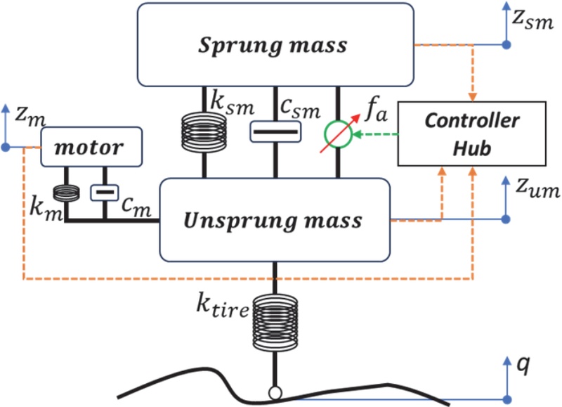
Concept of A-IWSS on quarter vehicle
where Zsm, Zum, Zm are the vertical displacement of sprung mass, unsprung mass, and motor respectively, while q is the road disturbance.
In Table 1, the parameters km and cm represent the equivalent stiffness and damping between the in-wheel motor and the unsprung mass, accounting for mounting flexibility and structural compliance in practical implementations.

Parameters of quarter A-IWSS model
According to control theory, the differential equation of the A-IWSS is transformed to state-space metric as (4).
| (4) |
We consider the state vector by the movement of suspension system, the speed of sprung mass, the displacement of tire to the road, the rapidity of unsprung mass, the dislocation of motor in comparison to unsprung mass, and the velocity of in-wheel motor as represented in (5)
| (5) |
Control and disturbance vectors are the damper force and the displacement from the road in (6)
| (6) |
3. System Design
3.1 System criteria
When crafting a controller, engineers have the task of creating a suspension control system that fulfills specific performance standards while prioritizing safety, comfort, and dependability across diverse driving scenarios. To achieve this, certain specifications must be meticulously considered:
Ride comfort: Assessing ride comfort involves measuring passenger acceleration, particularly within the 1–8 Hz frequency range, where sensitivity is highest.31) Motion smoothness depends on oscillation acceleration, considering both amplitude and frequency. Studying forced oscillations from road excitation requires precise acceleration analysis. Key experimental acceleration limits along the vehicle’s longitudinal, lateral, and vertical axes are as follows:
| (7) |
Road holding: Achieving optimal road grip necessitates maintaining consistent tire-road contact, which entails minimizing the transfer function from road disturbances to tire displacement (Zum - q) within a specific road profile. It’s important to note that maintaining a secure connection between tire and the road depends on keeping the dynamic tire load lower than the static load.
| (8) |
Suspension deflection: Maintaining suspension deflection within specified limits is crucial for optimal ride comfort and preventing structural damage. Deviating from these limits’ compromises comfort and vehicle performance. To prevent excessive suspension bottoming, it’s vital to recognize deflection constraints and take appropriate measures for peak performance:
| (9) |
Motor deflection: The deflection of the motor hub in A-IWSS refers to its movement resulting from external forces like bumps or vehicle manoeuvres. These systems, enabling each wheel to move independently, significantly improve ride comfort, handling, and traction. In terms of vibration frequencies, low-frequency vibrations (1-10 Hz) typically arise from larger road irregularities like potholes, while higher-frequency vibrations (10-50 Hz) can stem from smaller road imperfections and vehicle manoeuvres such as cornering and braking.
Controlled force: The damper generates a control force that is subject to saturation. It is theorized that the normalized control force is bounded, as indicated by the following inequality:
| (10) |
To evaluate vehicle ride comfort, it’s vital to minimize the Root Mean Square (RMS) value of vertical motor acceleration, sprung mass acceleration while also permitting suspension deflection, tire deflection, and the control signal to fluctuate within their predetermined limits.
| (11) |
3.2 LQR controller design
The control task is to identify factors with an unrecognized external impact on the road, the state variables are driven back to their desired values. In other words, oscillations generated by external factors must be swiftly suppressed. These problems can be guaranteed by using several control approaches. The output vector is selected in (12):
| (12) |
To improve the vehicle’s overall dynamic performance, it’s indeed crucial to take into account all of the assessment indications while building the LQR controller. Accordingly, the study defines the all-encompassing objective performance J as (13):
| (13) |
According to the process, the feedback gain matrix K of the LQR controller is represented as:
| (14) |
where the matrix is determined from the Ricatti calculation:
| (15) |
From the formulation (11) for the LQR controller, the cost function of the proposed model can be expressed as:
| (16) |
where ρ1, ρ2, ρ3, ρ4, ρ5, ρ6 are the weighting parameters for the objectives. These terms explicitly represent a multiobjective trade-off between ride comfort, road holding performance, and control effort. By that, the matrices Q, R, N in (13) is defined as
3.3 PSO algorithm finding the LQR weighting parameter
The determination of weighting matrix Q values typically involves a trial-and-error methodology, constrained by its reliance on the designer’s expertise and experience, despite the non-negativity constraint associated with these values. This conventional approach presents limitations due to its subjective nature and lack of systematic optimization. To overcome these challenges, advanced optimization techniques, such as PSO, have been employed to optimize the values of ρi in equation (16). Fig. 2 demonstrates the method of finding the optimal value for the Q matrix. It starts by initializing a population of particles randomly distributed in the solution space. By setting the cost function for the PSO problem as (17)
| (17) |
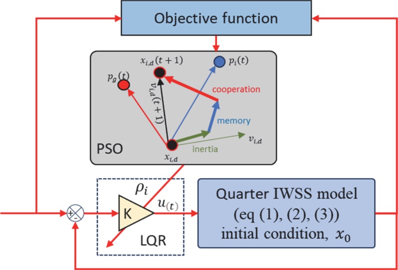
Optimizing process the weighting parameters for LQR controller
where w1, w2, w3, w4, w5, w6 are defined importance weights.
| (18) |
| (19) |
In each iteration, particles adjust their velocity as in (18) and position as in (19) based on their individual experiences and the best solutions found by the entire swarm. Through iterative refinement, PSO dynamically updates the swarm’s positions to converge towards the optimal solution. The algorithm terminates when a termination criterion, such as a maximum number of iterations or reaching a predefined fitness threshold, is met. PSO efficiently explores the solution space by leveraging collaboration and information exchange among particles, ultimately converging to a promising region where the optimal solution is likely to reside. This progress aims to identify optimal ρi values that satisfy the constraints outlined in equations (7) to (10), thereby addressing the specific requirements of the A-IWSS system. This systematic optimization methodology not only improves the robustness and effectiveness of controller design process but also ensures the attainment of unique Q values that align with the system's performance objectives.
Table 2 illustrates the weighting matrix values for the LQR controller, derived through both trial-and-error methodology and multi-objective optimization employing the PSO algorithm. Within this Table 2, the LQR row delineates the Q matrix values established via iterative experimentation, while the LQR-PSO row showcases the optimized Q matrix values obtained through automated multi-objective optimization utilizing the PSO algorithm. These optimized values frequently exhibit superior performance characteristics and are autonomously determined, minimizing the need for designer intervention.
The value of weighting parameters for control models
The PSO parameters were selected based on preliminary convergence evaluation, where MaxIt = 300 and nPop = 30, as in algorithm of Fig. 3, provided stable optimization performance with acceptable computational cost. Larger values resulted in only marginal objective-function improvement. Fig. 4 illustrates the resulting Best Cost for the designed problem. This configuration facilitates a thorough exploration of the solution space across 300 iterations, leveraging a population of 30 particles. The Best Cost representation in Fig. 4 provides insights into the performance characteristics of the optimal solution obtained through PSO optimization, where the multiple objectives of (16) are satisfied.
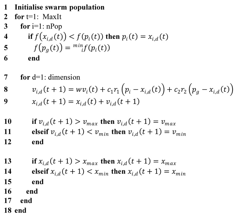
PSO algorithm finding the weighting parameters
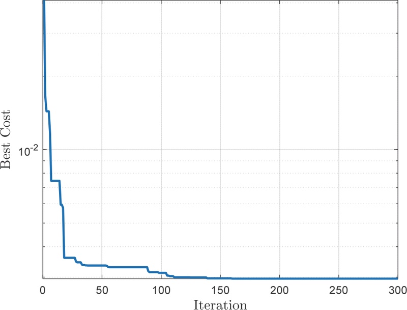
PSO fitting criteria
4. Simulation and Analysis
In modern control engineering, the combination of frequency-domain and time-domain analyses is essential for optimizing closed-loop systems. Frequency domain methods, such as Bode plots, assess stability and robustness, while time domain analysis refines transient response for desired dynamics. Bridging these domains enhances simulations, ensuring stability, performance, and robustness across varying conditions. This integrated approach, supported by extensive research, drives innovation in control system design.
4.1 Frequency domain analysis
Fig. 5 presents frequency domain responses of sprung mass velocity (a), unsprung mass velocity (b), wheel contact (c), suspension deflection (d), vertical motor displacement (e), and in-wheel velocity (f) under road surface excitation. The dashed sky-blue lines represent simulation results of the uncontrolled suspension system, while the red lines depict the A-IWSS system with LQR controller, and the dotted green lines represent simulation results when PSO combined with LQR for control. It is evident that the uncontrolled A-IWSS system easily undergoes resonant oscillations at low-frequency regions (7-10 rad/s), moderate-frequency regions (18-25 rad/s), and high-frequency regions (60-80 rad/s).
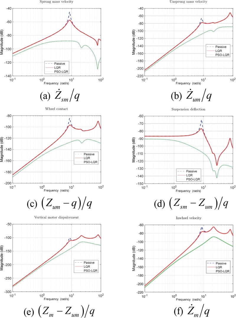
Frequency responds of sprung mass velocity (a), unsprung mass velocity (b), wheel contact (c), suspension deflection (d), vertical motor displacement (e), in wheel velocity (f)
With the A-IWSS system using the LQR controller, Fig. 5 shows effective low-frequency signal reduction by around 20 %, but limited impact in higher frequencies. The LQR-PSO controller outperforms, reducing all feedback transfer functions across the spectrum, optimally attenuating resonant oscillations and enhancing stability. These results highlight the potential of advanced control strategies for improving A-IWSS performance, reducing vibrations, and enhancing ride comfort.
4.2 Time domain analysis
In the simulation of the proposed model in the time domain, two distinct types of road surface excitations were applied to the A-IWSS system, as depicted in Fig. 6. The first scenario, illustrated in Fig. 6(a), employed a sinusoidal waveform with a 0.1 m amplitude and a frequency of 7rad/s to represent the road surface profile. Conversely, Fig. 6(b) showcased the road surface profile generated in accordance with the ISO8608-2016 standard, specifically Type C,32) simulating a speed of 50 km/h.
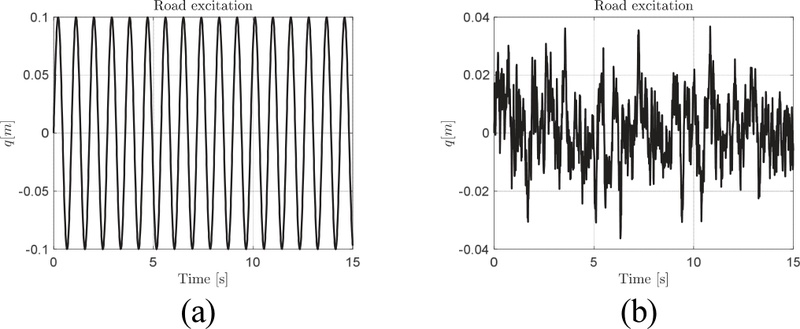
Desired road disturbance for simulation: sinewave (a), ISO-8608 (b)
Fig. 7 presents time-domain transfer functions for key system responses under sinusoidal road excitation. Without control, the suspended mass acceleration reaches nearly 2.3 m/s2. The LQR controller reduces this by approximately 22 %, while the LQR-PSO further lowers it to 1.6 m/s2. These results demonstrate the effectiveness of advanced control strategies in minimizing suspension oscillations and enhancing system performance.
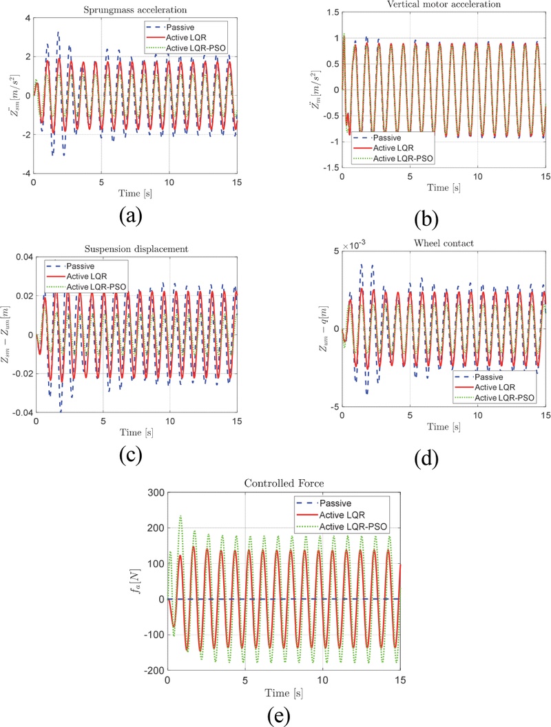
Time responds of sprung mass acceleration (a), vertical motor acceleration (b), suspension deflection (c), tire deflection (d), controlled force (e) with sinewave disturbance
The proposed controllers significantly reduce suspension displacement, improving workspace clearance and system layout. The LQR controller lowers displacement from 0.025m (Passive) to 0.021 m (16 % reduction), while the LQR-PSO further decreases it to 0.016 m—36 % less than the uncontrolled model and 23 % less than LQR alone. Road-holding performance also improves, with the LQR-PSO achieving the greatest reduction (30 %) in amplitude compared to the passive system.
Table 3 presents the RMS comparison for the proposed model. Compared to the passive system, the LQR controller reduces RMS values of suspended mass acceleration, vertical motor acceleration, suspension displacement, and unsprung mass displacement by 20.81 %, 4.59 %, 16.93 %, and 19.05 %, respectively. The LQR-PSO controller further enhances these reductions to 50.53 %, 8.24 %, 60.32 %, and 47.62 %. Compared to LQR alone, the LQR-PSO achieves additional reductions of 37.53 %, 3.82 %, 52.23 %, and 35.29 %, demonstrating its superior performance.
Comparison RMS values for sine-wave scenario
Fig. 8 illustrates the time response under ISO 8608-2016 Type C excitation at 50 km/h. The LQR-PSO model reduces suspended mass acceleration by 49.34 % and vertical motor acceleration by 16.23 % compared to the passive system. Suspension and unsprung mass displacements decrease by 53.13 % (from 0.95 m to 0.0047 m at 4.2 s) and 44.12 % (from 1.1 mm to 4.3 mm at 4.2 s), respectively. The LQR controller maintains control force below 30N, while the LQR-PSO peaks at 146 N, both within actuator operational limits. Considering practical electromechanical suspension actuators commonly reported for quarter-vehicle active suspension systems, the maximum control force of 146 N obtained in this study remains within feasible actuator operating capability. It should be noted that the increased control force observed in the LQR-PSO controller reflects a trade-off between ride comfort improvement and control energy consumption, which is inherent in active suspension systems.
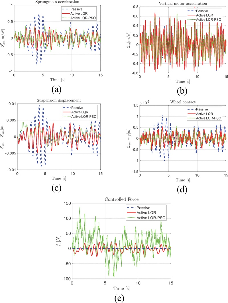
Time responds of sprung mass acceleration (a), vertical motor acceleration (b), suspension deflection (c), tire deflection (d), controlled force (e) with random disturbance
From Table 4, it is evident that the proposed LQR-PSO model demonstrates its superiority by completely attenuating the oscillation amplitudes of the suspended mass acceleration, vertical motor acceleration, vertical displacement of the suspension system, and relative displacement of the unsprung mass compared to the road surface. In this scenario, the most substantial reduction in displacement occurs notably in vertical displacement of suspension system, succeeded by the vertical motor acceleration, relative displacement of the unsprung mass, and suspended mass acceleration by 21.05 %, 16.16 %, 9.52 %, 8.32 %, respectively, relative to the LQR model.
Comparison RMS values for ISO8608-2016 scenario
5. Conclusion
In this research, the A-IWSS with a PSO-optimized LQR controller offers significant advantages. It provides adaptive control by dynamically adjusting suspension parameters based on varying driving conditions, road surfaces, and vehicle loads. The optimization via PSO ensures continuous tuning of the LQR controller’s weighting parameters, accounting for real-time changes in vehicle and road conditions. Additionally, the system excels in optimizing trade-offs between multiple objectives, such as ride comfort, handling, and energy efficiency, leading to improved overall vehicle performance. These capabilities contribute to a promising solution for enhancing ride quality, handling, and energy efficiency, as evidenced by reductions in suspended mass acceleration (49.34 %), suspension displacement (53.13 %), and unsprung mass displacement (44.12 %). It should be noted that the present study evaluates handling performance primarily through vertical tire–road contact within a quarter-vehicle framework, while comprehensive assessment of lateral, yaw, and roll dynamics requires extension to a full-vehicle model.
Nomenclature
| msm : | sprung mass, kg |
| mum : | wheel mass, kg |
| mm : | motor mass, kg |
| ksm : | suspension stiffness, N/m |
| csm : | suspension damping coefficient, Ns/m |
| km : | stiffness of damper for motor, N/m |
| cm : | damping coefficient for motor, Ns/m |
| ktire : | tire stiffness, N/m |
| : | vertical displacement of sprung mass, m/s2 |
| : | vertical velocity of sprung mass, m/s |
| Zsm : | vertical displacement of sprung mass, m |
| : | vertical acceleration of unsprung mass, m/s2 |
| : | vertical velocity of sprung mass, m/s |
| Zum : | vertical displacement of unsprung mass, m |
| fa : | controller force, N |
| : | vertical acceleration of motor, m/s2 |
| : | vertical velocity of motor, m/s |
| Zm : | vertical displacement of motor, m |
| Zsm - Zum : | suspension travel, m |
| Zm - Zum : | displacement of motor-unsprung mass, m |
| Zum - q : | tire-road contact, m |
| q : | road disturbance, m |
Acknowledgments
The author sincerely thanks Electric Power University for their invaluable support and assistance, which greatly contributed to the study’s success.
References
-
M. Belrzaeg, A. A. Ahmed, M. M. Khaleel, A. Alsharif, M. M. Rahmah and A. S. D. Alarga, “Suspension System Control Process for Buses with In-Wheel Motors,” Engineering Proceedings, Vol.29, No.1, Paper No.4, 2023.
[https://doi.org/10.3390/engproc2023029004]

- D. T. Tu, Active In-Wheel Suspension System Design for On-Road Vehicles, CRC Press, 2026.
-
L. Jin, Y. Yu and Y. Fu, “Study on the Ride Comfort of Vehicles Driven by In-Wheel Motors,” Advances in Mechanical Engineering, Vol.8, No.3, Paper No.1687814 016633622, 2016.
[https://doi.org/10.1177/1687814016633622]
-
D. T. Tu, “Active in-Wheel Suspension Performance Analysis Using Linear Quadratic Controllers,” 2023 International Conference on Control, Robotics and Informatics (ICCRI), pp.1-6, IEEE, 2023.
[https://doi.org/10.1109/ICCRI58865.2023.00008]
-
L. Meng, Y. Zou, Y. Qin and Z. Hou, “A New Electric Wheel and Optimization on Its Suspension Parameters,” Proceedings of the Institution of Mechanical Engineers, Part D: Journal of Automobile Engineering, Vol.234, No.12, pp.2759-2770, 2020.
[https://doi.org/10.1177/0954407020921736]
-
H. Salmani, M. Abbasi, T. Fahimi Zand, M. Fard and R. Nakhaie Jazar, “A New Criterion for Comfort Assessment of In-Wheel Motor Electric Vehicles,” Journal of Vibration and Control, Vol.28, No.3-4, pp.316-328, 2022.
[https://doi.org/10.1177/1077546320977187]
-
F. Ballo, R. Frizzi, G. Mastinu, D. Mastroberti, G. Previati and C. Sorlini, “Lightweight Design and Construction of Aluminum Wheels,” SAE 2016 World Congress and Exhibition 217486, 2016.
[https://doi.org/10.4271/2016-01-1575]
-
W. Skarka, W. Kocoń, R. Skoberla and A. Bzymek, “Innovative Suspension System Integrated to the Wheel Rim for Lightweight Vehicle,” Transdisciplinary Engineering for Complex Socio-technical Systems, Vol.10, pp.409-418, 2019.
[https://doi.org/10.3233/ATDE190147]
-
P. Dukalski, B. Będkowski, K. Parczewski, H. Wnęk, A. Urbaś and K. Augustynek, “Dynamics of the Vehicle Rear Suspension System with Electric Motors Mounted in Wheels,” Eksploatacja i Niezawodność – Maintenance and Reliability, Vol.21, No.1, pp.125-136, 2019.
[https://doi.org/10.17531/ein.2019.1.14]
-
W. Lu, W. Li and X. Chen, “Design Optimization of an Integrated E-Type Multilink Suspension Wheel-Side Drive System and Improvement of Vehicle Ride Comfort,” Shock and Vibration, Vol.2021, No.1, Paper No.1462980, 2021.
[https://doi.org/10.1155/2021/1462980]
-
X. Xu, M. Wang, P. Xiao, J. Ding and X. Zhang, “In-Wheel Motor Control System for Four-Wheel Drive Electric Vehicle Based on CR-GWO-PID Control,” Sensors, Vol.23, No.19, Paper No.8311, 2023.
[https://doi.org/10.3390/s23198311]
-
M. Liu, Y. Zhang, J. Huang and C. Zhang, “Optimization Control for Dynamic Vibration Absorbers and Active Suspensions of In-Wheel-Motor-Driven Electric Vehicles,” Proceedings of the Institution of Mechanical Engineers, Part D: Journal of Automobile Engineering, Vol.234, No.9, pp.2377-2392, 2020.
[https://doi.org/10.1177/0954407020908667]
-
L. Li, S. Kang and J. Deng, “Design and Parameter Optimization of a New Type In-Wheel Motor Drive Electric Vehicle Vibration Reduction System,” Journal of Vibroengineering, Vol.26, No.2, pp.401-413, 2023.
[https://doi.org/10.21595/jve.2023.23551]
-
T. Feng and L. Shu, “Game-Based Multiobjective Optimization of Suspension System for In-Wheel Motor Drive Electric Vehicle,” Mathematical Problems in Engineering, Vol.2021, No.1, Paper No.5589199, pp.1-13, 2021.
[https://doi.org/10.1155/2021/5589199]
-
R. Zhai, P. Xiao, R. Zhang and J. Ju, “In-Wheel Motor Control System Used by Four-Wheel Drive Electric Vehicle Based on Whale Optimization Algorithm-Proportional–Integral–Derivative Control,” Advances in Mechanical Engineering, Vol.14, No.6, Paper No.16878132221104574, 2022.
[https://doi.org/10.1177/16878132221104574]
-
L. Hott, V. Ivanov, K. Augsburg, V. Ricciardi, M. Dhaens, M. Al Sakka, K. Praet and J. V. Molina, “Ride Blending Control for AWD Electric Vehicle with In-Wheel Motors and Electromagnetic Suspension,” 2020 IEEE Vehicle Power and Propulsion Conference (VPPC), pp.1-5, IEEE, 2020.
[https://doi.org/10.1109/VPPC49601.2020.9330946]
-
F. Jia, H. Jing, Z. Liu and M. Gu, “Cooperative Control of Yaw and Roll Motion for In-Wheel Motor Vehicle with Semi-Active Suspension,” Proceedings of the Institution of Mechanical Engineers, Part D: Journal of Automobile Engineering, Vol.236, No.1, pp.3-15, 2022.
[https://doi.org/10.1177/09544070211020827]
-
M. Anaya-Martinez, J. J. Lozoya-Santos, L. C. Félix-Herrán, J. C. Tudon-Martinez, R.-A. Ramirez-Mendoza and R. Morales-Menendez, “Control of Automotive Semi-Active MR Suspensions for In-Wheel Electric Vehicles,” Applied Sciences, Vol.10, No.13, Paper No.4522, 2020.
[https://doi.org/10.3390/app10134522]
-
D. T. Tu, “Optimizing Vehicle Ride Comfort Using GALQR Control in In-Wheel Suspension Systems,” Engineering, Technology & Applied Science Research, Vol.15, No.2, pp.21306-21312, 2025.
[https://doi.org/10.48084/etasr.9684]
-
V. Vidal, P. Stano, G. Tavolo, M. Dhaens, D. Tavernini, P. Gruber and A. Sorniotti, “On Pre-Emptive In-Wheel Motor Control for Reducing the Longitudinal Acceleration Oscillations Caused by Road Irregularities,” IEEE Transactions on Vehicular Technology, Vol.71, No.9, pp.9322-9337, 2022.
[https://doi.org/10.1109/TVT.2022.3172172]
-
W. Wang, M. Niu and Y. Song, “Integrated Vibration Control of In-Wheel Motor-Suspensions Coupling System via Dynamics Parameter Optimization,” Shock and Vibration, Vol.2019, No.1, Paper No.3702919, 2019.
[https://doi.org/10.1155/2019/3702919]
-
Z. Zhang, W. Zhao, C. Wang and L. Li, “Stability Control of In-Wheel Motor Electric Vehicles under Extreme Conditions,” Transactions of the Institute of Measurement and Control, Vol.41, No.10, pp.2838-2850, 2019.
[https://doi.org/10.1177/0142331218814899]
-
N. E. H. Yazid, T. M. Chikouche, K. Hartani and A. Merah, “Advanced Vertical and Lateral Coupling Dynamics Control for a Four In-Wheel Motor Drive Electric Vehicle,” Periodica Polytechnica Electrical Engineering and Computer Science, Vol.67, No.1, pp.21-39, 2023.
[https://doi.org/10.3311/PPee.20545]
-
T. Suzuki, F. Chauvicourt and H. Fujimoto, “High-Bandwidth Suspension Resonance Analysis of In-Wheel Motor Vehicle Using Multibody Dynamics,” 2021 IEEE International Conference on Mechatronics (ICM), pp.1-6, IEEE, 2021.
[https://doi.org/10.1109/ICM46511.2021.9385653]
-
S. D. Puma-Araujo, R. Galluzzi, X. Sánchez-Sánchez and R. A. Ramirez-Mendoza, “Study of Viscoelastic Rubber Mounts on Vehicle Suspensions with In-Wheel Electric Motors,” Materials, Vol.14, No.12, Paper No.3356, 2021.
[https://doi.org/10.3390/ma14123356]
-
Z. Zhao, L. Zhang, J. Wu, L. Gu and S. Li, “Vertical-Longitudinal Coupling Effect Investigation and System Optimization for a Suspension-In-Wheel-Motor System in Electric Vehicle Applications,” Sustainability, Vol.15, No.5, Paper No.4168, 2023.
[https://doi.org/10.3390/su15054168]
-
L. Zhang, C. Ren, X. Yuan and W. Zhang, “Ride Comfort Control of In-Wheel Motor Drive Unmanned Ground Vehicles with Energy Regeneration,” Proceedings of the Institution of Mechanical Engineers, Part D: Journal of Automobile Engineering, Vol.235, No.4, pp.1057-1069, 2021.
[https://doi.org/10.1177/0954407020933364]
-
X. Jin, J. Wang, S. Sun, S. Li, J. Yang and Z. Yan, “Design of Constrained Robust Controller for Active Suspension of In-Wheel-Drive Electric Vehicles,” Mathematics, Vol.9, No.3, Paper No.249, 2021.
[https://doi.org/10.3390/math9030249]
-
H. Wu, L. Zheng, Y. Li, Z. Zhang, Y. Liang and Y. Hu, “Comprehensive Analysis for Influence of Complex Coupling Effect and Controllable Suspension Time Delay on Hub-Driving Electric Vehicle Performance,” Proceedings of the Institution of Mechanical Engineers, Part D: Journal of Automobile Engineering, Vol.236, No.1, pp.40-58, 2022.
[https://doi.org/10.1177/09544070211018555]
-
L. Zhang, S. Zhang and W. Zhang, “Multi-Objective Optimization Design of In-Wheel Motors Drive Electric Vehicle Suspensions for Improving Handling Stability,” Proceedings of the Institution of Mechanical Engineers, Part D: Journal of Automobile Engineering, Vol.233, No.8, pp.2232-2245, 2019.
[https://doi.org/10.1177/0954407018783145]
- International Organization for Standardization, ISO 2631-5: Mechanical Vibration and Shock — Evaluation of Human Exposure to Whole-Body Vibration, ISO 2631-5, 2018.
- International Organization for Standardization, ISO 8608:2016 Mechanical Vibration — Road Surface Profiles — Reporting of Measured Data, ISO 8608:2016, 2016.