
Online Error Calibration of Rotor Position Sensor for Automotive Electric Actuator Based on Permanent Magnet Synchronous Motor
Copyright Ⓒ 2026 KSAE / 249-11
This is an Open-Access article distributed under the terms of the Creative Commons Attribution Non-Commercial License(http://creativecommons.org/licenses/by-nc/3.0) which permits unrestricted non-commercial use, distribution, and reproduction in any medium provided the original work is properly cited.
Abstract
Position sensor errors in permanent magnet synchronous motors (PMSMs) generate torque ripple and degrade system efficiency. Conventional offline calibration methods, however, are limited by high costs and the inability to recalibrate in the field. This paper proposes an online calibration technique that utilizes the motor’s coasting operation without requiring additional hardware. The initial offset is estimated using the d-q axis voltages under a zero-current control condition, and a virtual reference angle is obtained from the back electromotive force (back EMF) during coasting. Particularly, to address the continuous decrease in speed and the resulting frequency variation during the coasting phase, an adaptive notch filter (ANF) is employed to effectively eliminate second-order harmonic errors caused by factors such as those resulting from rotor eccentricity. The extracted errors are stored in a look-up table (LUT) for real-time position compensation across the entire speed range. Experimental results demonstrate that the proposed method achieves position tracking performance comparable to that of a high-resolution encoder.
Keywords:
Permanent magnet synchronous motor(PMSM), Position sensor error, Online calibration, Adaptive notch filter(ANF), Back electromotive force(Back EMF), Eccentricity1. Introduction
Permanent Magnet Synchronous Motor (PMSM) is widely used in various electrification systems such as electric vehicles, industrial robots, and home appliances based on its high-power density and excellent dynamic characteristics and control efficiency. In order to stably implement PMSM's high-performance field-oriented control (FOC), accurate rotor flux position information of the rotor must be identified in real time, and for this purpose, high-precision mechanical position sensors such as resolvers or high-resolution encoders are generally used. Recently, in automotive electrification systems, in order to miniaturize the system and reduce costs, non-contact magnetic sensor-based methods, such as Hall sensors and magnetoresistance sensors, which detect position by attaching sensor magnets to the ends of the motor's rotating shafts, are being applied to replace conventional mechanically coupled position sensors, such as resolvers and high-resolution encoders.1)
These position sensors have position measurement errors due to physical limitations such as mechanical assembly tolerances during the mass production process.2,3) The position error of the sensor is mainly manifested as a constant offset and a second harmonic component that fluctuates depending on the rotation period. This creates distortion of the d-q axis coordinate transformation of the electric motor, affecting the current control loop, ultimately leading to increased torque ripple, reduced acceleration performance, and reduced overall efficiency of the system.4,5)
Generally, in order to correct errors in such position sensors, a test bed environment combining a dynamometer to drive the target motor at a constant speed and a high-precision encoder to provide an absolute position reference is essential. However, this offline calibration method significantly increases manufacturing cost and inspection time in the mass production process. Moreover, if the sensor error changes due to physical wear or temperature changes after the motor system is actually installed in the field or mounted on the vehicle, it has a fatal limitation in that it cannot be recalibrated in real time.6) Additionally, existing online calibration performs driving and calibration simultaneously. Therefore, since the back electromotive force (back EMF) must be estimated with phase current flowing, a state observer that depends on motor parameters such as resistance (R) and inductance (L) is essential, and has the limitation of being very vulnerable to parameter changes.
To overcome these existing limitations, this paper proposes a technique for online correction of position sensor errors by utilizing the motor's coasting section without additional equipment, relying solely on an internal controller algorithm. First, the initial assembly offset of the sensor is dynamically estimated by applying arctangent operation to the d-q axis voltage (vd, vq) error components detected in the zero current control state. Second, the three-phase back EMF measured in the same coasting section is converted to a Cartesian coordinate system to derive a virtual reference angle. At this time, an adaptive notch filter (ANF) was applied to the proposed algorithm to precisely track and eliminate only the positional second harmonic error components even in a variable frequency environment due to three-phase back EMF imbalance due to rotor eccentricity and speed reduction.7) The extracted error components are stored in the form of a look-up table (LUT) and used to compensate for position values in real time in the entire speed range.
To verify the validity of the technique proposed in this paper, experiments were conducted on a 1 kW actuator. The improvement in the distortion rate of the three-phase current waveform before and after error correction was analyzed. As a result, it was confirmed that the proposed technique can enhance the reliability of the entire system by effectively suppressing current harmonics and torque ripple caused by position sensor errors.
2. Position Sensor Errors and Offline Correction
A shaft-end mounted position sensor is a non-contact position sensor that detects the rotor position and speed by attaching a sensor magnet to the end of a rotating shaft and placing a position sensor IC on the corresponding stationary part. This method is widely used in various motor drive systems due to its simple structure, low cost, and excellent durability. The fixed position sensor detects periodic variations in magnetic field distribution that occur when the sensor magnet rotates along with the rotating shaft, and generally outputs these as analog or digital signals in the form of sin/cos to calculate the absolute position of the rotor.
The absolute rotor information obtained in this manner is the most critical element for high-performance control of the PMSM. Examining the general position sensor-based PMSM control structure in Fig. 2, it can be seen that the angular information acquired from the sensor is directly applied to the speed calculator and d-q axis coordinate transformations (Park and Inverse Park Transformations). Therefore, accurate position information must be provided to perform accurate d-q axis current control.
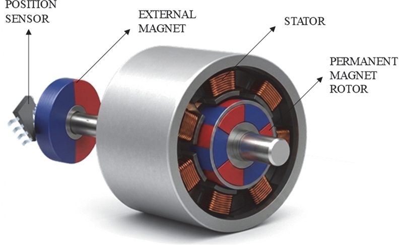
PMSM with shaft-end mounted position sensor and sensor magnet
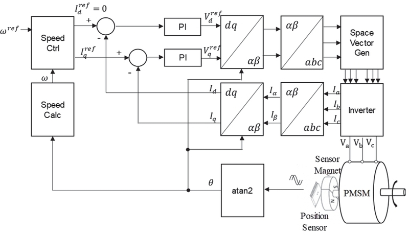
Control block diagram of position sensor-based PMSM
2.1 Position Sensor Errors
Axial-mounted position sensors calculate the rotor position using the orthogonal flux component of the sensor magnet attached to the rotor. In the ideal case, the measured flux is expressed as follows.
| (1) |
Here, the estimated position at this time is as follows.
| (2) |
In this case, the magnetic flux trajectory is circular and the estimated rotor position matches the actual position, so no error occurs. However, in Hall sensor-based position detection, various measurement errors can occur due to mechanical alignment errors, the most common cause of which is the eccentricity of the position sensor.8)
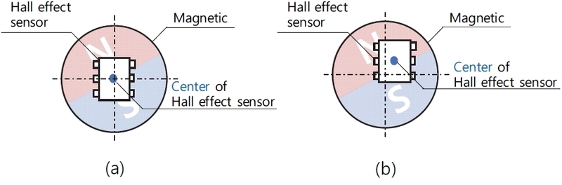
Position sensor structures: (a) normal state, (b) eccentric state
Eccentricity refers to a state in which the rotation center of the sensor magnet attached to the end of the rotation axis and the measurement center of the position sensor do not coincide and are mechanically misaligned. This eccentricity occurs due to manufacturing tolerances, assembly errors, etc. and inevitably occurs in actual systems.
If position sensor eccentricity exists, the magnetic field distribution recognized by the sensor will differ from the ideal case, resulting in distortion of the position signal. In particular, the ideal sin/cos signal contains additional harmonic components, which lead to position estimation. This distortion is not a simple offset or scale change, but the following types of errors occur.
| (3) |
Here, k represents the amplitude of the error, and ϕ represents the phase offset of the error. Fig. 4 shows the position error waveform caused by this eccentricity. The position errors due to eccentricity manifest including periodic harmonic ripple dominated by phase offset and second harmonics.
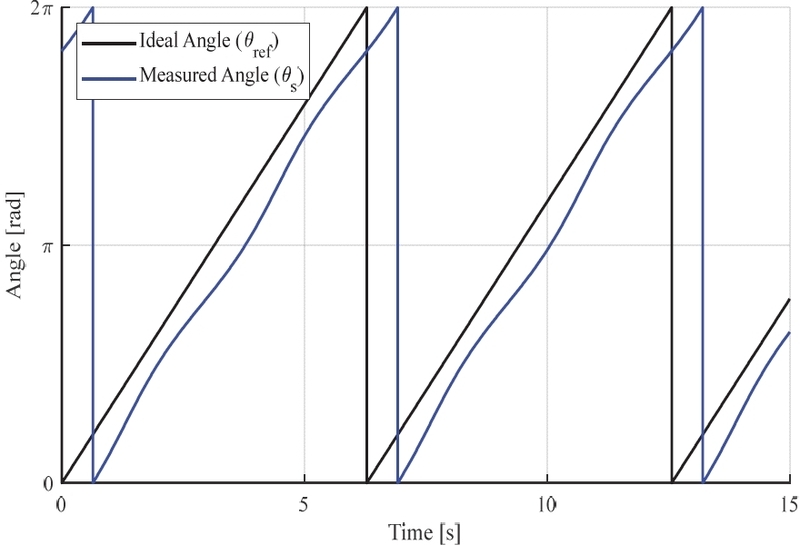
Angle measurement error waveform due to eccentricity
Such errors directly affect the control performance of position sensor-based PMSM drive systems. If errors are included in the position sensor values, the entire current control loop is affected, resulting in degraded control performance and increased torque ripple.9,10)
| (4) |
2.2 Offline Correction of Position Sensor Errors
As shown in Fig. 5, the offline correction method for compensating for position sensor errors involves using the driving motor of a dynamometer to rotate the target motor at a constant speed and obtaining an absolute reference angle through a high-precision encoder. The error data for each angle derived from this is then constructed into a lookup table to correct the position sensor error in real time during operation. This method requires the construction of a separate, complex testbed in the mass production process, which not only significantly increases manufacturing costs and inspection time but also has limitations in that errors cannot be recorrected on-site if they fluctuate due to temperature changes or mechanical wear after the motor is installed in an actual vehicle or industrial site.
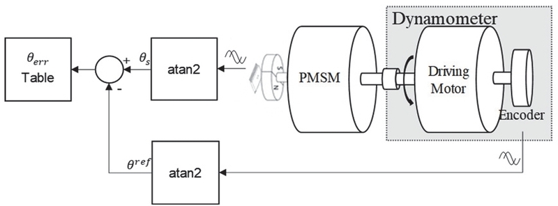
Conventional position sensor error measurement
3. Online Compensation Method for Position Sensor Errors
3.1 Online Compensation of Position Sensor Offset Errors
To compensate for the phase offset caused by mechanical assembly errors during the installation of the position sensor, a zero-current control technique during the coasting state is employed.11)
In a general synchronous rotation d-q coordinate system, the PMSM voltage equations are expressed as follows:
| (5) |
When the motor is operated in the coasting state and controlled such that id = 0 and iq = 0 (zero-current control), the voltage equations are ideally simplified as follows:
| (6) |
In other words, in an ideal alignment state where there is no phase offset in the sensor, the d-axis voltage becomes 0, and only the back EMF proportional to the rotation speed of the motor should appear in the q-axis voltage. Assuming that there is an offset of Δθ between the actual rotor position θ and the position θs measured by the position sensor due to the mechanical assembly error of the position sensor, the relationship is as follows:12)
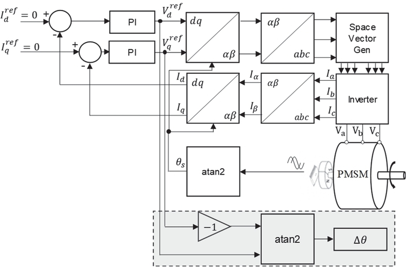
Position sensor offset measurement
| (7) |
Due to this phase offset Δθ, in the estimated coordinate system recognized by the controller, the back EMF component that actually exists only on the q-axis is projected onto the d-axis and q-axis, respectively.
| (8) |
Using the d-q axis voltage measured during zero current control, the sensor's offset Δθ can be directly calculated through the arctangent function as follows:
| (9) |
By applying the estimated Δθ as a compensation value to the position detection logic, the controller can perform precise torque control based on an accurate d-q coordinate system.
3.2 Online Compensation Method for Position Sensor Harmonic Errors
The online compensation of position sensor harmonic errors is a software-based technique that automatically compensates for position sensor errors using only the control and estimation algorithms of the motor drive controller, without requiring an additional motor or a high-precision encoder. The virtual reference angle is estimated using the three-phase back EMF. The detected back EMF is converted to a rectangular coordinate system (Clarke Transform) and then an arctangent operation is performed to derive the reference angle.
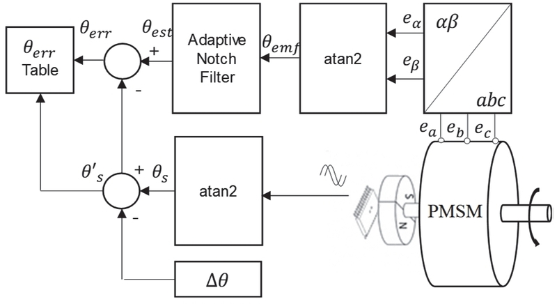
Bloc diagram of error compensation table
Imbalance in back EMF may occur due to magnetic flux imbalance (magnetization imbalance), winding end-turn imbalance, etc.13) The formula for ideal three-phase back EMF (ideal back EMF) is as follows.
| (10) |
| (11) |
| (12) |
In contrast, when back EMF imbalance is present, the amplitudes of the three-phase back EMF, Aa, Ab, and Ac, are unequal, and if the coefficients for converting this to a stationary coordinate system are defined as K1, K2, and K3, it is developed as follows:
| (13) |
| (14) |
| (15) |
| (16) |
| (17) |
| (18) |
| (19) |
When calculating the arc tangent of the α − β axis voltage including the imbalance coefficients K1, K2, and K3 as shown in the above equation, an elliptical trajectory is drawn rather than an ideal circular trajectory. As a result, a periodic error with a second harmonic component compared to the actual rotor position occurs in the estimated angle θest. When eccentricity exists, the position estimation error is not a simple static error, but appears as a periodic error with a second harmonic component, which can degrade the performance of the position estimator and controller.
In situations where the motor driving voltage is applied, it is impossible to directly measure the pure back EMF due to the influence of inverter switching and the applied voltage. Therefore, back EMF measurement must be performed during the deceleration phase where the motor rotates due to inertia.
To eliminate harmonic error components (second harmonics) generated during this measurement process, a notch filter that attenuates only specific frequency bands can generally be utilized. The transfer function G(s) of a typical second harmonic removal notch filter is expressed as follows:14)
| (20) |
Here, ωc is the center frequency (notch frequency) to be cut off, and ζ is the damping ratio, a parameter that determines the cutoff bandwidth and depth of the filter. As can be seen from the Bode plot in Fig. 8, the notch filter has the characteristic of effectively removing frequency components by rapidly reducing only the gain (magnitude) of the set center frequency band.15)
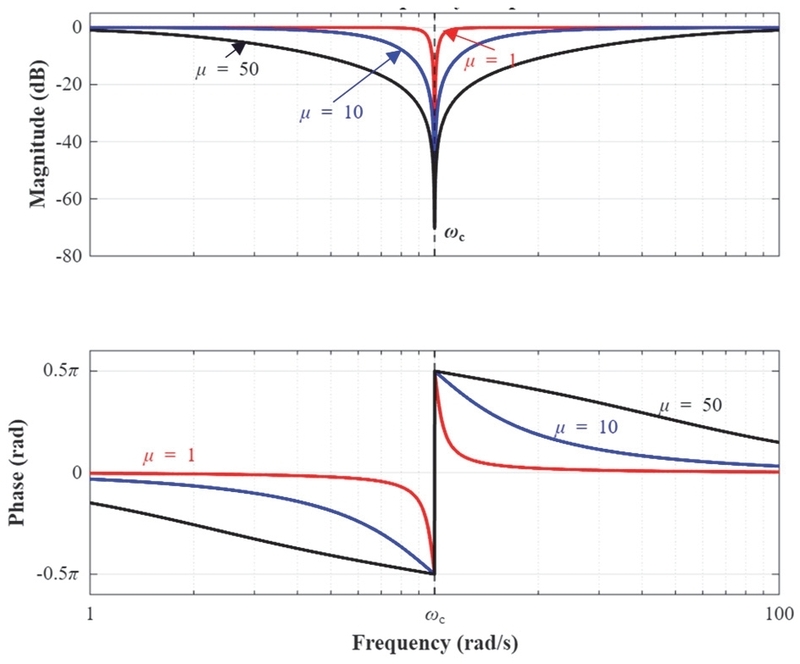
Notch filter bode plot
However, during the inertia deceleration phase, the rotational speed of the motor continuously decreases, so the frequency of the second harmonic ripple included in the position angle error also fluctuates. If the center frequency ωc in the above equation is fixed at a constant, the filter may deviate from the target frequency band as the speed changes, resulting in attenuation of frequency components other than the second harmonic components. Therefore, to effectively accommodate variable frequency environments, it is essential to employ a control structure that adjusts the notch filter center frequency, ωc, in real time as a function of the motor electrical angular velocity, ωe, by synchronizing it according to ωc = 2ωe.
To implement this approach, an ANF corresponding to frequency changes was used. Fig. 9 shows a block diagram of the proposed variable frequency-responsive ANF.
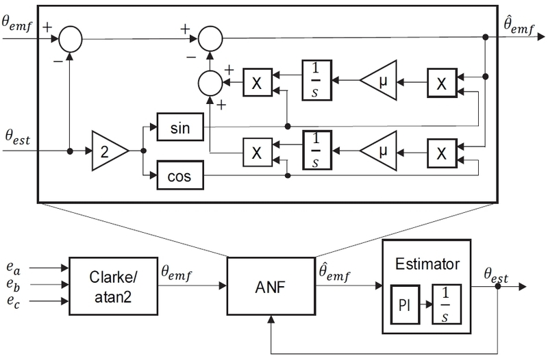
Block diagram of ANF-based position estimation
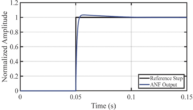
Verification of tracking performance and convergence speed of the ANF according to the damping ratio
The signal used as the input to the ANF is constructed by receiving the back EMF-based position angle, θemf and the filtered and estimated position angle, θest as feedback signals. The second harmonic component to be eliminated fluctuates in conjunction with the electrical angular velocity, ωe. To compensate this component, the estimated fundamental position angle, θest is multiplied by 2 to generate two mutually orthogonal variable reference signals, x1(t) and x2(t).
| (21) |
This reference signal generation method performs the same role mathematically as varying the center frequency, ωc, of the previously mentioned transfer function as a function of 2ωe. In other words, it ensures that the cutoff frequency of the ANF tracks the actual second harmonic frequency even when the motor decelerates.
Based on the variable reference signals, the Least Mean Square (LMS) algorithm is applied to continuously update two weights and for estimating the amplitude of the second harmonic component. The weight update is defined by the following integral formula.
Here, μ is a parameter that determines the bandwidth of the ANF, and the PI gain of the Estimator determines the convergence characteristics of the estimated angle. As the value of μ increases, the response speed of the filter improves, but the notch characteristics become smoother, which may degrade harmonic removal performance; conversely, if the value of μ is excessively small, sufficient error compensation cannot be achieved within the deceleration section. Furthermore, if the PI gain is excessively small, the convergence of the estimated angle is delayed, and if it is excessively large, it may track residual harmonic components, leading to increased oscillation of the estimated angle. In this study, μ = 10, Kp = 1000, and Ki = 40000 were applied to simultaneously secure stable error compensation and rapid convergence of the estimated angle during the deceleration section. These parameters were selected by comprehensively considering the convergence speed of the position estimation error and steady-state ripple, and a settling time of approximately 0.05 seconds or less and stable steady-state characteristics were secured.
| (22) |
The final output formula is as follows:
| (23) |
Finally, the filtered position change amount derived through ANF passes through the PI controller and integrator inside the subsequent estimator, causing the error component to converge to zero, and as a result, a filtered estimated position angle θest with the second harmonic component suppressed can be obtained.
3.3 Overall Structure of the Proposed Error Compensation
The overall control diagram of the PMSM incorporating the previously described adaptive notch filter-based online reference angle estimation technique is shown Fig. 11. The proposed error compensation algorithm has a structure that extracts the sensor's position error during the coasting section to construct a table or derives an error model function through curve fitting. This error information is used for position compensation during normal operation, and the error compensation procedure is as follows:
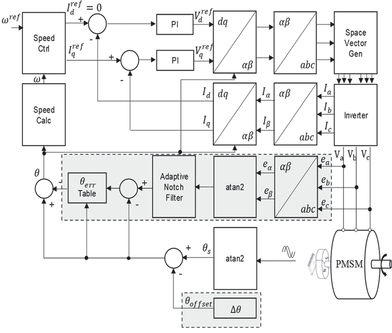
Block diagram of the proposed error compensation
First, the offset caused by the mechanical assembly tolerance of the position sensor is corrected using Δθ estimated through zero-current control. The sensor's zero point is initially aligned by subtracting the offset compensation value Δθ from the angle θs measured by the sensor.
Second, the three-phase back EMF generated during coasting is transformed into coordinates and an arctangent operation is performed to derive the back EMF-based reference angle. The corresponding angle passes through ANF to eliminate second harmonic error components, generating a high-purity virtual reference angle, .
Third, the deviation between the zero-aligned sensor angle θs and the ANF-filtered back EMF-based reference angle is computed to extract the periodic error component θerr, which arises from factors such as sensor mechanical eccentricity. The extracted error data is mapped to the mechanical position of the rotor and stored within the controller in the form of a table (θerr Table), or it is converted into a continuous error model function through curve fitting techniques for use.
Finally, during normal operation of the motor, the final control angle θ is derived by subtracting the error value calculated through the data stored in the table or the curve fitting function from the angle acquired by the position sensor.
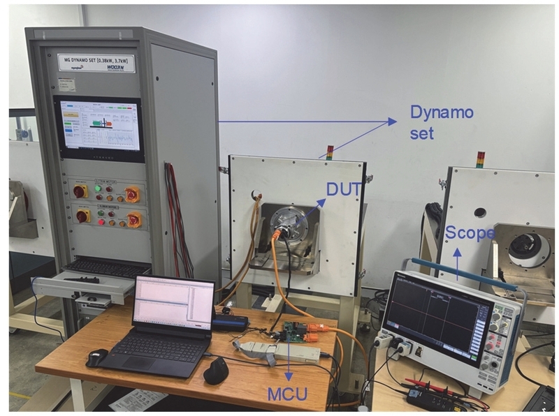
Configuration of motor test bench
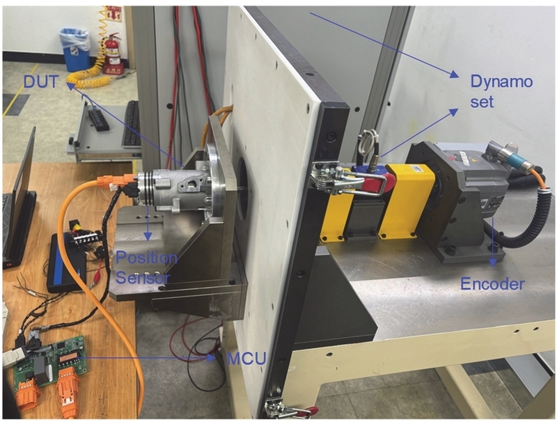
Configuration of motor test bench
By applying this position θ, in which both harmonic distortion and offset are compensated, to the speed controller and coordinate converter, current distortion and torque ripple caused by sensor errors can be effectively reduced.
4. Experimental results
4.1 Experimental environment configuration
An electric motor driving experiment was conducted to verify the proposed adaptive error compensation algorithm. The experimental setup is shown in Fig. 1 and Fig. 2, and the main specifications of the motor used in this experiment and the parameters of the control system are summarized in Table 1 and Table 2 below.

Specifications of motor
Specifications of experimental system
The position measurement error caused by the assembly eccentricity of the actual sensor magnet and position sensor, which is basically inherent in the manufacturing and mass production process of the test motor, was compensated and the results were verified.
First, to verify the performance of the back EMF-based estimated angle filtered through ANF, the reference angle of the high-precision encoder was compared with the back EMF-based estimated angle. By comparing the estimated angle based on back EMF and the position sensor output value for which precision was secured, the angle error caused by the eccentricity of the position sensor was derived. Afterwards, the position sensor angle was compensated based on the derived error, and the harmonic distortion rate of the phase current waveform was compared to confirm the reduction in position error before and after compensation.
4.2 Experimental results and analysis
In order to reproduce the actual driving environment where back EMF imbalance exists in the experiment, a 3 % magnitude error was applied to the three-phase back EMF, and based on this, the position estimation error before and after applying the algorithm was compared and analyzed.
To simulate the section where the motor rotates and decelerates by inertia after the inverter switching is blocked, the rotation speed of the dynamo side motor coupled with the test motor was set to exponentially decrease according to time t (RPM = 3000 * e-2t). The results of measured speed response are shown in Fig. 12.
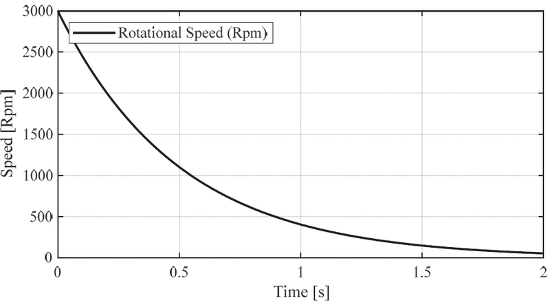
PMSM Rotational speed (RPM)
The reference angle θ measured by the high-precision encoder on the dynamo side and the estimated angle θemf before ANF application, derived from the back EMF applied with a 3 % error are shown in Fig. 13. The results of comparing the angle estimation errors before and after ANF application by plotting the errors (θ − θemf) and (θ − θest) for the reference angle θ on the same graph are shown in Fig. 14.
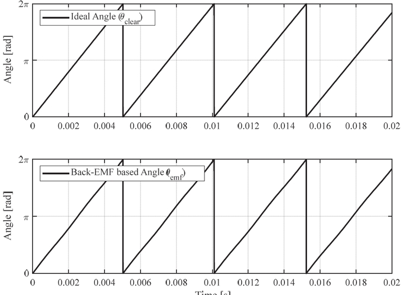
Comparison between the ideal angle and back EMF based angle
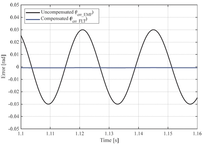
Comparison of position angle error before and after compensation
Through the comparison of position estimation errors in Fig. 13, it can be seen that a second harmonic ripple with an amplitude of 0.03 rad exists due to the back EMF error simulation before ANF application, but the amplitude converges to near zero after ANF application. This confirms that the adaptive mechanism of ANF, which updates the center frequency in real time even under conditions of motor speed fluctuation, attenuates only the second harmonic component caused by back EMF imbalance. Therefore, it can be confirmed that the back EMF-based estimated angle θemf compensated through ANF has an estimation accuracy almost identical to that of θ measured by a high-precision encoder and thus possesses a level of reliability capable of replacing the reference angle.
When driving at 2,000 rpm constant speed, Fig. 15(a) shows mechanical and electrical angles, and Fig. 14 (b) shows the position error waveform. Since the number of pole pairs is 5, the electric angle has a frequency that is 5 times faster than the mechanical angle, as confirmed by the period comparison in Fig. 14(a). As a result of analyzing the error components in Fig. 14(b) by filtering out high-frequency components using a low-pass filter, errors in the form of second harmonics relative to the mechanical angle were predominantly observed. This causes the electrical 5th and 7th harmonic components inherent in the three-phase drive system to be strongly amplified due to the influence of the 2nd/5th low-frequency electric angle in a system with 5 pole pairs.
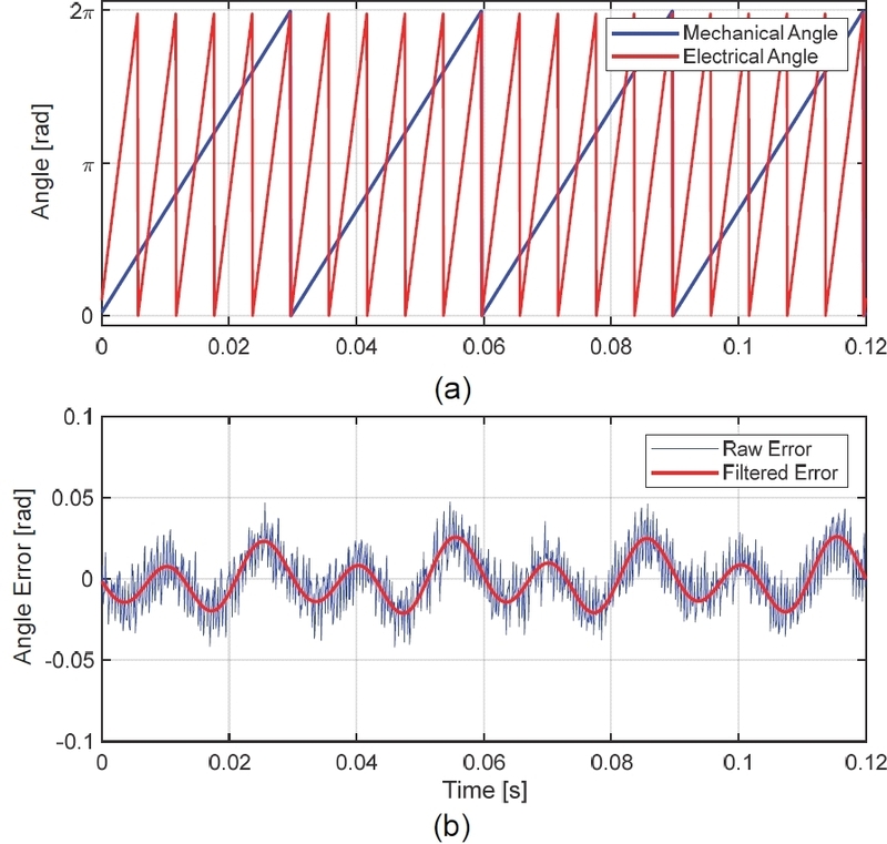
(a) Mechanical angle and electrical angle, (b) angle error and low-pass filtered error
The position error data obtained through the experiment is as shown in Fig. 16. The error model function formulated using the curve fitting technique based on the obtained data is as shown in Eq. (24).
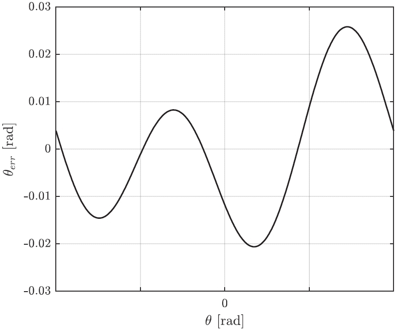
Position error table for angle compensation
| (24) |
Fig. 15 is a position error table or error function, and the phase current waveform before and after compensating for the angle error is as shown in Fig. 17.
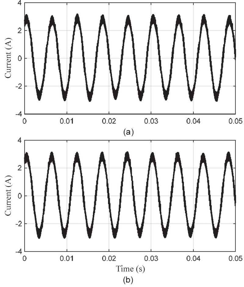
Measured phase current waveforms (a) before error compensation, (b) after error compensation
The phase current waveform measured before the application of the error compensation technique is shown in Fig. 16(a), and the phase current waveform measured after the application of the error compensation technique is shown in Fig. 16(b). Since it is difficult to quantitatively verify the reduction in phase current ripple after error compensation, the phase current waveform was analyzed using Fast Fourier Transform (FFT). The analysis results are shown in Fig. 18.
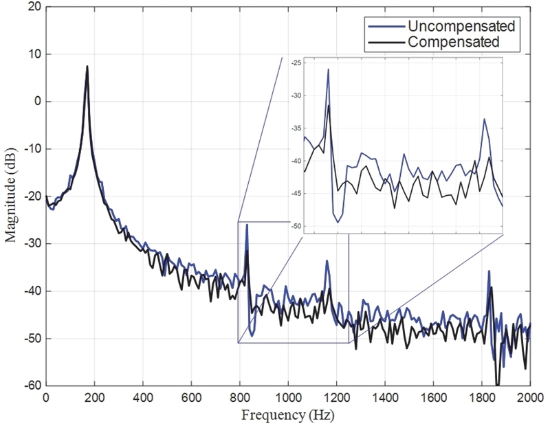
Comparison of phase current FFT spectra with and without error compensation
Through the FFT analysis results of the phase current in Fig. 17, it was confirmed that the position error in the form of the 2nd harmonic relative to the mechanical angle manifests as 5th and 7th harmonic components relative to the electrical angle. As a result of applying the proposed error compensation technique to the system to compensate for the position error relative to the mechanical angle, it was verified through actual experiments that the magnitudes of the 5th (833.3 Hz) and 7th (1166.7 Hz) harmonic components included in the phase current relative to the fundamental wave (166.7 Hz) were reduced by more than 5 dB, respectively, compared to before compensation.
To quantitatively evaluate the performance of this proposed technique, the THD was calculated by considering odd harmonic components up to the 17th order relative to the fundamental wave, as shown in the following formula:
| (25) |
The calculated Total Harmonic Distortion (THD) results are shown in Fig. 19. The results showed that the THD before applying the compensation technique was approximately 2.846 %, but after applying the proposed technique, the THD decreased to approximately 1.716 %, confirming that the harmonic distortion of the phase current was significantly reduced.
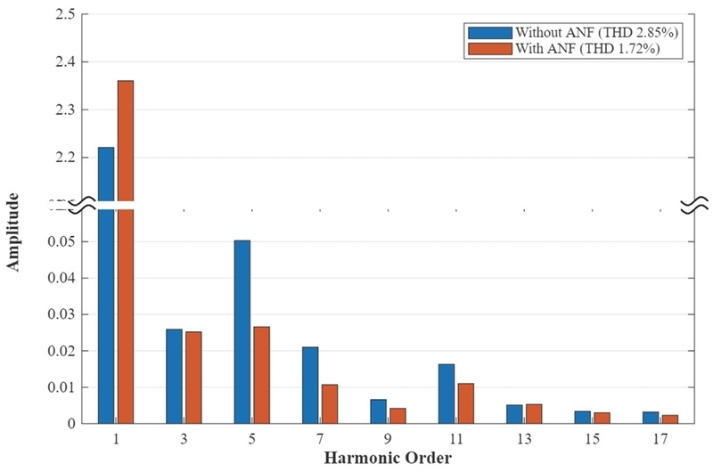
Comparison of phase current THD with and without error compensation
5. Conclusion
This paper proposed an algorithm to compensate online for mechanical errors in position sensors occurring in permanent magnet synchronous motor drive systems. The proposed technique estimates position error by utilizing the back EMF measured during the motor's coasting section and compensates for the position error by extracting the second harmonic component through an ANF, even in a variable frequency environment. Using the proposed technique, position error was estimated during the coasting and deceleration phases of a 1 kW electric actuator, and an error table was stored. Subsequently, the current control performance was experimentally verified by applying the error compensation technique under FOC control conditions. As a result, the phase current waveform improved before and after compensation. Furthermore, FFT and THD analyses were performed for quantitative verification, confirming that the THD value decreased from 2.846 % to 1.716 %. This experimentally demonstrated that current ripple phenomena caused by factors such as mechanical eccentricity of the sensor can be suppressed.
This proposed technique has the advantage of improving the control stability and waveform quality of the entire system without the need for offline calibration processes that require replacing expensive high-precision sensors or additional equipment. Therefore, applying the error compensation technique proposed in this study to the system can improve vibration and noise, along with reducing efficiency caused by harmonics.
Nomenclature
| e : | back-electromotive force, V |
| i : | current, A |
| v : | voltage, V |
| G : | transfer function |
| θ : | rotor position angle, rad |
| Δθ : | position offset error, rad |
| ω : | angular velocity, rad/s |
| ζ : | damping ratio |
| Subscripts | |
|---|---|
| c : | center |
| e : | electrical |
| err : | error |
| est : | estimated |
| FLT : | filtered |
| ref : | reference |
| s : | sensor |
Acknowledgments
This study was supported by Changwon National University (2025–2026). This research was also financially supported by the Institute of Civil-Military Technology Cooperation through a grant funded by the Defense Acquisition Program Administration (DAPA) and the Ministry of Trade, Industry and Resources of the Republic of Korea (Grant No. 22-CM-EC-36).
References
-
C. Datlinger and M. Hirz, “Benchmark of Rotor Position Sensor Technologies for Application in Automotive Electric Drive Trains,” Electronics, Vol.9, No.7, Paper No.1063, 2020.
[https://doi.org/10.3390/electronics9071063]

-
A. Gebregergis, M. Chowdhury, M. Islam and T. Sebastian, “Modeling of Permanent Magnet Synchronous Machine Including Torque Ripple Effects,” 2013 IEEE Energy Conversion Congress and Exposition (ECCE), pp.2108-2114, 2013.
[https://doi.org/10.1109/ECCE.2013.6646967]
-
X. Wu, Z. Q. Zhu, Z. Y. Wu, T. Y. Liu and Y. X. Li, “Analysis and Suppression of Rotor Eccentricity Effects on Fundamental Model Based Sensorless Control of Permanent Magnet Synchronous Machine,” IEEE Transactions on Industry Applications, Vol.56, No.5, pp.4896-4905, 2020.
[https://doi.org/10.1109/TIA.2020.2997297]
-
L. Zhong, M. F. Rahman, W. Y. Hu and K. W. Lim, “Analysis of Direct Torque Control in Permanent Magnet Synchronous Motor Drives,” IEEE Transactions on Power Electronics, Vol.12, No.3, pp.528-536, 1997.
[https://doi.org/10.1109/63.575680]
-
D. Jung, “Design of Driving Motor for Small Electric Vehicle Using Low Voltage Battery,” Transactions of KSAE, Vol.30, No.1, pp.83-89, 2022.
[https://doi.org/10.7467/KSAE.2022.30.1.083]
-
Y. Oh, J. Park, C. Shin, J. Jung and J. Lee, “Forced Alignment-Based Motor Position Sensor Error Identification and Compensation Technique to Reduce Second-Order Torque Ripple,” 2025 IEEE International Electric Machines & Drives Conference (IEMDC), pp.1304-1310, 2025.
[https://doi.org/10.1109/IEMDC60492.2025.11061169]
-
G. Wang, H. Zhan, G. Zhang, X. Gui and D. Xu, “Adaptive Compensation Method of Position Estimation Harmonic Error for EMF-Based Observer in Sensorless IPMSM Drives,” IEEE Transactions on Power Electronics, Vol.29, No.6, pp.3055-3064, 2014.
[https://doi.org/10.1109/TPEL.2013.2276613]
-
J. K. Kim and C. S. Lee, “Angular Position Error Detection of Variable Reluctance Resolver Using Simulation-Based Approach,” Int. J. Automotive Technology, Vol.14, No.4, pp.651-658, 2013.
[https://doi.org/10.1007/s12239-013-0070-7]
-
R. Ramakrishnan, A. Gebregergis, M. Islam and T. Sebastian, “Effect of Position Sensor Error on the Performance of PMSM Drives for Low Torque Ripple Applications,” 2013 International Electric Machines & Drives Conference (IEMDC), pp.1166-1173, 2013.
[https://doi.org/10.1109/IEMDC.2013.6556307]
-
R. Raja, T. Sebastian, M. Wang, A. Gebregergis and M. S. Islam, “Effect of Position Sensor Error on the Performance of Permanent Magnet Machine Drives,” IEEE Transactions on Industry Applications, Vol.53, No.6, pp.5518-5526, 2017.
[https://doi.org/10.1109/TIA.2017.2704898]
-
K. Choi, Y. Kim, S. K. Kim and K. S. Kim, “Auto-Calibration of Position Offset for PMSM Drives with Uncertain Parameters,” Electronics Letters, Vol.56, No.20, pp.1048-1051, 2020.
[https://doi.org/10.1049/el.2020.1669]
-
S. S. Kuruppu, S. G. Abeyratne and S. Hettiarachchi, “Modeling and Detection of Dynamic Position Sensor Offset Error in PMSM Drives,” IEEE Access, Vol.11, pp.34336-34347, 2023.
[https://doi.org/10.36227/techrxiv.20480904]
-
D. G. Dorrell, M. Popescu and D. M. Ionel, “Unbalanced Magnetic Pull Due to Asymmetry and Low-Level Static Rotor Eccentricity in Fractional-Slot Brushless Permanent-Magnet Motors with Surface-Magnet and Consequent-Pole Rotors,” IEEE Transactions on Magnetics, Vol.46, No.7, pp.2675-2685, 2010.
[https://doi.org/10.1109/TMAG.2010.2044582]
-
J. Kang, “Resonance Frequency Estimation of Tire for Detecting Decrease in Tire Inflation Pressure,” Transactions of KSAE, Vol.27, No.11, pp.847-852, 2019.
[https://doi.org/10.7467/KSAE.2019.27.11.847]
- D. J. Ahn, K. H. Park, S. H. Kim and H. D. Nam, “Design of Fuzzy Logic Adaptive Filters for Active Mufflers,” Transactions of KSAE, Vol.19, No.4, pp.84-90, 2011.