
승용 자동차 BLDC 통풍블로워 제어기 개발 연구
Copyright Ⓒ 2026 KSAE / 249-07
This is an Open-Access article distributed under the terms of the Creative Commons Attribution Non-Commercial License(http://creativecommons.org/licenses/by-nc/3.0) which permits unrestricted non-commercial use, distribution, and reproduction in any medium provided the original work is properly cited.
Abstract
This study presents the development of a Brushless DC (BLDC) ventilation blower controller for passenger vehicle HVAC systems and the verification of its performance under automotive electrical environments. System requirements were analyzed, and a controller incorporating BLDC drive hardware, a field-oriented control (FOC) algorithm, CAN communication, and diagnostic functions was designed. The controller was evaluated through bench and environmental tests that considered voltage variation, temperature conditions, and electromagnetic compatibility. The experimental results show that the developed controller achieves approximately 20 % higher efficiency and 5–8 dB(A) noise reduction compared to a conventional brushed motor system while maintaining a sufficient thermal margin of the power devices. In addition, the controller satisfies CISPR 25 Class 4 electromagnetic emission requirements, demonstrating its applicability to passenger vehicle HVAC systems. This work provides a practical design and validation methodology for automotive BLDC ventilation blower controllers.
Keywords:
BLDC motor, Ventilation blower, Automotive HVAC, FOC control, Electromagnetic interference, Automotive controller키워드:
브러시리스 직류 모터, 통풍블로워, 자동차 공조, FOC 제어, 전자파, 차량용 제어기1. 서 론
자동차 HVAC 시스템에서 통풍블로워는 공기 순환과 열 관리를 담당하는 핵심 구성 요소이다. 기존 브러시 모터 기반 블로워는 효율 및 내구성 측면에서 한계가 있어, 최근에는 BLDC 기반 시스템으로 전환되고 있다. BLDC 통풍블로워 제어기는 모터 구동뿐 아니라 차량 통신, 진단 기능, 전자파 적합성 등 다양한 전장 요구조건을 동시에 만족해야 한다. 본 연구에서는 승용 자동차용 BLDC 통풍블로워 제어기를 설계하고, 센서리스 제어 기반 성능을 실험적으로 검증하였다.
차량용 전도 및 결합 전기적 교란 요구사항은 ISO 7637-2 규격을 따른다.1) 또한 차량용 기능 안전 요구사항은 ISO 26262 규격을 따른다.2)
2. 시스템 구성
본 연구에서 사용된 BLDC 모터의 주요 사양은 다음과 같다.

BLDC motor specification
본 연구에서 시스템 효율은 전원 입력 전력 대비 모터의 기계적 출력 전력의 비로 정의하였다.
η = (Pout / Pin) × 100
여기서 입력 전력(Pin)은 공급 전압과 전류를 측정하여 계산하였으며, 출력 전력(Pout)은 토크와 회전속도를 이용하여 산출하였다. 회전속도는 엔코더를 이용하여 측정하였으며, 모든 측정은 정상 상태 조건에서 수행하였다.
Fig. 1은 BLDC 통풍블로워 제어기의 전체 구조를 나타낸다. 제어기는 차량 배터리로부터 전원을 입력받아 EMI 필터 및 보호 회로를 거쳐 인버터를 통해 모터를 구동하며, CAN 통신을 통해 차량과 데이터를 교환한다.
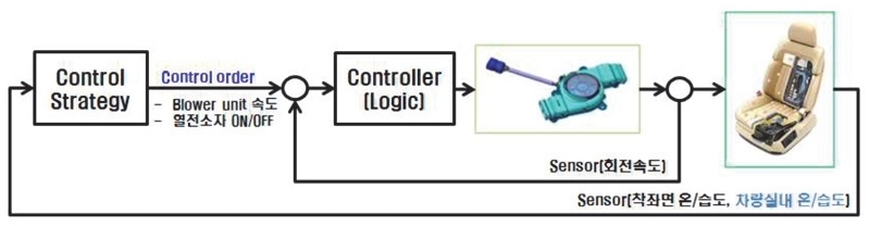
Overall block diagram of a BLDC ventilation blower controller for passenger vehicles
차량용 BLDC 블로워 제어기 개발 사례와 차량용 모터 드라이브 시스템의 EMI 대응 설계 방법은 기존 연구에서 제시된 바 있다.3,4)
3. 제어 알고리즘
본 연구에서 사용된 제어 알고리즘은 BLDC 모터 구동에 널리 사용되는 FOC(Field Oriented Control) 기반 벡터 제어 방식이다. 속도 제어 루프에서 목표 속도와 실제 속도의 오차를 기반으로 q축 기준 전류(Iq*)를 생성하며, d축 전류(Id)는 0으로 설정하였다. 본 연구의 FOC 기반 벡터 제어 구조는 BLDC 및 PMSM 모터 구동에 널리 사용되는 제어 방식에 기반하며,5) 자동차용 BLDC 블로워 제어기에도 적용되고 있다.3)
센서리스 제어에서는 BEMF(Back Electromotive Force, 역기전력)를 이용하여 회전자 위치를 추정하였다. 저속 영역에서는 오픈루프 전류 제어로 기동한 뒤, 일정 속도 이상에서 BEMF 검출이 가능해지면 폐루프 제어로 전환하였다.
Fig. 2는 MCU 주변 회로 구성을 나타낸다. 해당 회로는 전류 센싱, PWM 생성 및 CAN 통신 인터페이스를 포함한다.
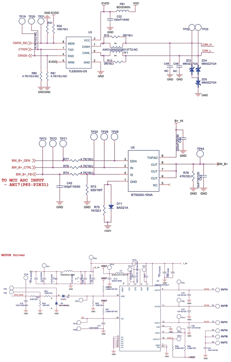
MCU peripheral interface circuit
Fig. 3은 PCB artwork를 나타낸다. 전원 및 신호 패턴을 분리하여 EMI를 저감하도록 설계하였다.
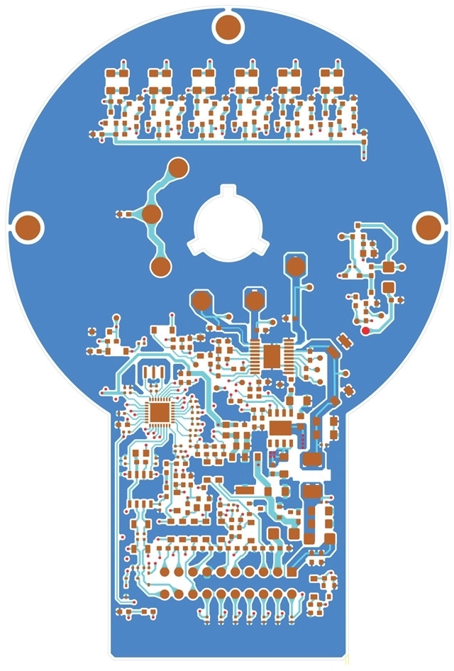
PCB artwork
Fig. 4는 FOC 제어 알고리즘 구조를 나타낸다. 제어기는 d축 및 q축 전류를 제어하여 목표 속도를 추종한다.
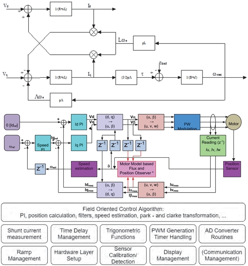
FOC(Vector) control algorithm
Fig. 5는 BEMF 기반 센서리스 제어 구조를 나타낸다. 회전자 위치는 Zero crossing 검출과 PLL 기반 위상 추정을 이용하여 산출한다.
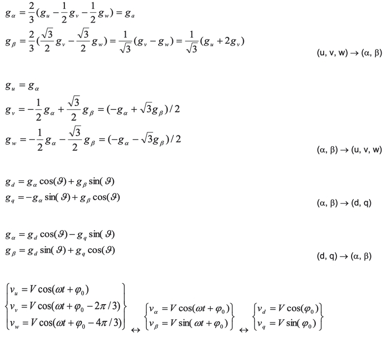
Zero crossing and closed loop
Fig. 6은 BLDC 통풍블로워 제어기에 적용된 벡터 제어 모델을 나타낸다. 본 모델은 전류 및 속도 제어 루프를 기반으로 d축 및 q축 전류를 제어하여 목표 속도를 안정적으로 추종하도록 구성된다.
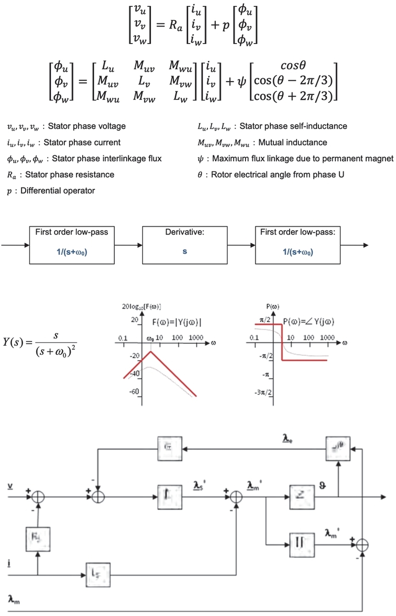
Vector control and control model
Fig. 7은 펌웨어에서 구현된 모터 시동 절차를 나타낸다. 기동 초기에는 BEMF 검출이 어려우므로 오픈루프 전류 제어 방식으로 모터를 가속시킨다. 이후 일정 속도 이상에서 BEMF 검출이 가능해지면 센서리스 폐루프 제어로 전환하여 안정적인 속도 제어를 수행한다.
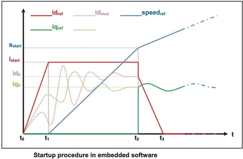
Startup procedure in firmware
4. 시험 방법
시험은 벤치 환경 및 환경 챔버를 이용하여 수행하였다. 시험 장치는 BLDC 통풍블로워 모듈, DC 전원공급기, 전류 프로브, 온도 측정 장비, 소음 측정기, 데이터 로거 및 CAN 분석 장비로 구성하였다.
시험 조건은 다음과 같다.
- 공급 전압: 11 V, 13.5 V, 16 V
- 주변 온도: 25 °C, -20 °C, 60 °C
- 속도 명령: 30 %, 50 %, 80 %, 100 %
- 소음 측정 거리: 1 m
- 시험 항목: 속도 응답, 입력 전류, 시스템 효율, 소음, MOSFET 온도 및 EMI 방사 특성으로 구성하였다. 모든 측정은 동일 조건에서 반복 수행하였으며, 분석에는 평균값을 사용하였다.
5. 시험 결과 및 고찰
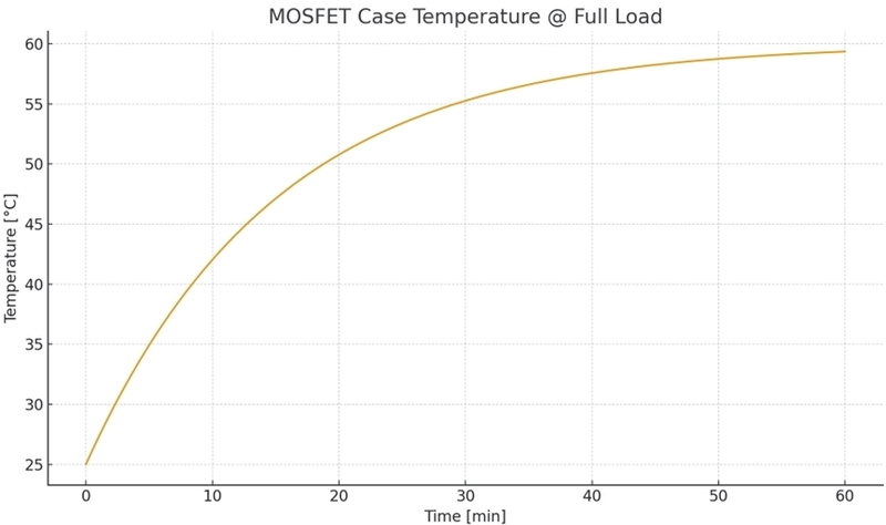
본 시험 결과는 자동차 전장 부품에서 일반적으로 허용되는 MOSFET 접합 온도 기준(150 °C)을 고려할 때 충분한 열 신뢰성을 확보함을 보여준다. 측정 결과 MOSFET 케이스 온도는 정격 부하 조건에서 80 °C 이하로 유지되어 열적 안전 여유가 확보되었다.
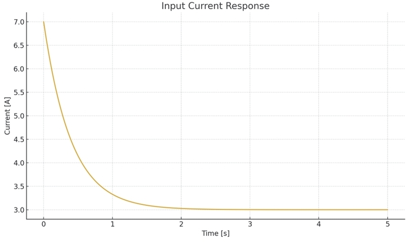
Figs. 8, 9는 0 %→100 % 속도 명령 입력 시 BLDC 통풍 블로워의 회전 속도 및 입력 전류 응답 측정 결과를 나타낸다. 모터는 약 1 s 이내에 목표 속도에 도달하였으며, 기동 시 최대 전류는 정격의 약 1.8배 수준으로 제한되었다.
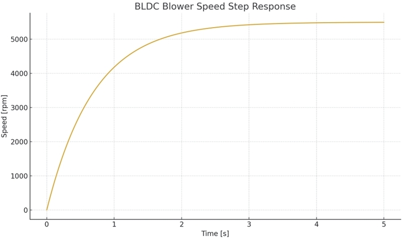
Step response of BLDC ventilation blower speed
Startup current response of a BLDC ventilation blower
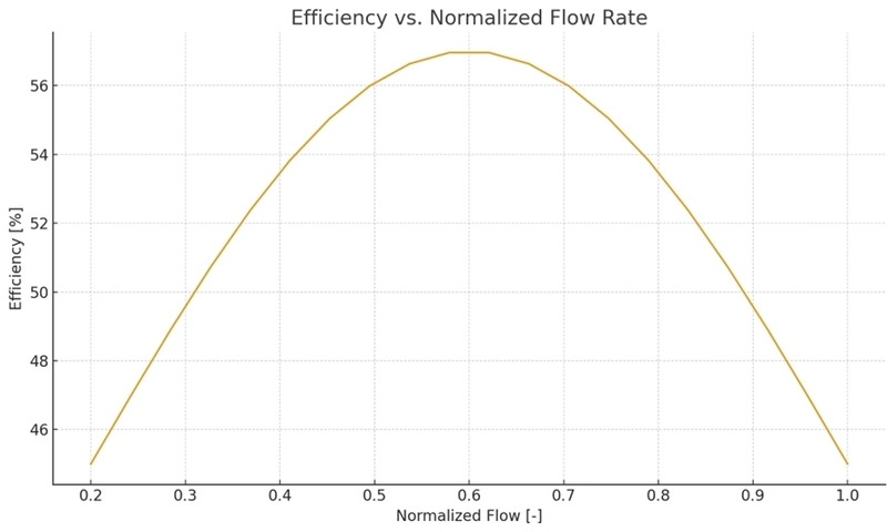
Fig. 10은 정규화된 유량에 따른 시스템 효율 측정 결과를 나타낸다. 효율은 중간 유량 구간에서 최대값을 나타내며, 이는 해당 구간에서 모터 및 구동 시스템의 운전 효율이 가장 높은 상태임을 의미한다.
System efficiency–flow rate characteristics of a ventilation blower
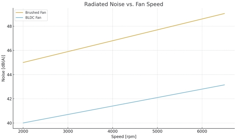
Fig. 11은 기존 브러시 모터 기반 통풍블로워와 본 연구에서 개발한 BLDC 통풍블로워의 소음 수준을 비교한 측정 결과를 나타낸다. 동일 속도 조건에서 BLDC 시스템은 약 5 ~ 8 dB(A) 낮은 소음 수준을 보였다.
Noise comparison between brushed motor and BLDC ventilation blower
Fig. 12는 정격 부하 조건에서 MOSFET 케이스 온도 상승 측정 결과를 나타낸다. 주변 온도 25 °C에서 약 60분 구동 시 정상 상태 온도는 80 °C 이하로 수렴하였으며, 이는 소자 정격 대비 충분한 온도 마진을 확보한 결과이다.
MOSFET case temperature rise under rated load
차량용 전자파 요구사항은 CISPR 25 규격을 따르며,6) 본 연구의 하드웨어 구성은 해당 요구조건을 만족하도록 설계되었다.
6. 결 론
본 연구에서는 승용 자동차용 BLDC 통풍블로워 제어기를 설계하고, 그 성능을 실험적으로 검증하였다. 제어기는 FOC 기반 센서리스 제어를 통해 안정적인 구동 특성을 보였으며, 기존 브러시 모터 기반 시스템 대비 효율 향상 및 소음 저감 효과를 확인하였다. 또한 열 특성 평가 결과 MOSFET 온도는 허용 범위 내에서 안정적으로 유지되어 차량 적용 가능성을 확인하였다. 본 연구 결과는 승용 자동차용 BLDC 통풍블로워 제어기의 설계 및 검증을 위한 실용적인 방법을 제시한다.
Nomenclature
| A : | effective cross-sectional area, m2 |
| I : | phase current, A |
| Id : | d-axis current, A |
| Iq : | q-axis current, A |
| N : | rotational speed, rpm |
| Pout : | mechanical output power, W |
| Pin : | electrical input power, W |
| T : | electromagnetic torque, N·m |
| Vdc : | DC link voltage, V |
| η : | system efficiency, % |
| BEMF : | back electromotive force |
| UDS : | unified diagnostic services |
| Subscripts | |
|---|---|
| d : | direct axis |
| q : | quadrature axis |
| in : | input |
| out : | output |
| ref : | reference value |
| max : | maximum value |
| rated : | rated condition |
References
- ISO 7637-2, “Road vehicles – Electrical disturbances from conduction and coupling,” 2011.
- ISO 26262, “Road vehicles – Functional safety,” 2018.
- S. J. Lee, “Development of Automotive BLDC Blower Controller,” Transactions of KSAE, Vol.31, No.4, pp. 321-329, 2023.
- J. H. Kim, “EMI Characteristics of Automotive Motor Drive Systems,” Transactions of KSAE, Vol.30, No.2, pp. 145-152, 2022.
- R. Krishnan, “Permanent Magnet Synchronous and Brushless DC Motor Drives,” CRC Press, 2010.
- CISPR 25, “Radio disturbance characteristics for the protection of receivers used on board vehicles,” 2016.