
Adaptive Fuzzy-PID Control of Nonlinear Air Suspension for Performance Enhancement in Heavy-Duty Trucks
Copyright Ⓒ 2026 KSAE / 248-01
This is an Open-Access article distributed under the terms of the Creative Commons Attribution Non-Commercial License(http://creativecommons.org/licenses/by-nc/3.0) which permits unrestricted non-commercial use, distribution, and reproduction in any medium provided the original work is properly cited.
Abstract
Enhancing ride comfort and road-holding in heavy-duty trucks is challenging. Moreover, nonlinear air suspension dynamics and conflicting performance objectives make controller design difficult. While conventional proportional-integral-derivative (PID) control offers improvements, its fixed-gain structure limits adaptability under varying road and load conditions. Accordingly, this study proposed a novel adaptive control strategy that synergizes a PID controller with a fuzzy logic system to dynamically adjust gains in real-time. To do this, a high-fidelity nonlinear model of a quarter-truck equipped with an air suspension system was developed and subjected to an ISO8608-2016 Class B road profile at 60 km/h. Simulation results demonstrate the superior performance of the proposed Fuzzy-PID controller among passive, conventional PID, and standalone fuzzy control systems. The hybrid controller achieves a good compromise between comfort and stability, reducing sprung mass acceleration by 59.2 % to reduce vertical acceleration, improving ride comfort and road-holding by minimizing the dynamic tire load by 35.3 % compared to the passive benchmark. Furthermore, it operates with the lowest control force requirement, indicating greater energy efficiency. The findings establish that the Fuzzy-PID architecture effectively navigates the classic performance trade-off, providing a robust and intelligent solution for advanced automotive suspension systems that demand superior comfort and stability.
Keywords:
Air suspension system, Fuzzy-PID control, Ride comfort, Road-holding, Vehicle dynamics and control, Heavy truck1. Introduction
The pursuit of optimal dynamic performance in commercial vehicles remains a central focus of automotive engineering, driven by escalating demands for ride quality, handling stability, and operational safety. Heavy-duty trucks, characterized by significant payload variations and exposure to diverse road profiles, present particularly challenging design constraints for suspension systems.1) While passive suspension architectures offer mechanical simplicity, their inherent compromise between ride comfort and road holding has motivated extensive research into active and semi-active alternatives.2-4) Among these, air suspension systems have gained prominence due to their superior adaptability, self-leveling capability, and inherent vibration isolation properties compared to conventional steel spring arrangements.5-8)
The development of effective control strategies for air suspension systems must account for their fundamental nonlinear characteristics, including gas thermodynamics, flow dynamics through interconnecting pipelines, and amplitude-dependent stiffness properties.8-10) Early research efforts focused primarily on conventional PID control, valued for its implementation simplicity and reliability in linear systems.11–13) However, the fixed-gain nature of classical PID controllers proves inadequate for handling the parameter variations and nonlinear dynamics inherent in air suspension systems operating under real-world conditions.11)
Subsequent investigations have explored intelligent control paradigms to address these limitations. Fuzzy logic control (FLC) has demonstrated considerable success in managing system nonlinearities without requiring precise mathematical models. Sun et al.14) showed that fuzzy-based controllers can effectively adapt to changing operating conditions, though they may lack the systematic tuning procedures available for conventional controllers. The integration of optimization methodologies with control design has emerged as a powerful approach for performance enhancement. Genetic Algorithms (GA), Particle Swarm Optimization (PSO), and other metaheuristic techniques have been successfully applied to optimize controller parameters, demonstrating significant improvements in suspension performance metrics.6)
Recent advances have further expanded the control design landscape. Adaptive control strategies, including Model Reference Adaptive Control (MRAC) and adaptive neural networks, have been developed to compensate for system uncertainties and time-varying parameters.12,13,15,16) Robust control techniques such as H∞ control and sliding mode control have been employed to ensure performance consistency despite modeling inaccuracies and external disturbances.5,17-19) Predictive control frameworks, particularly Model Predictive Control (MPC), have shown promise in handling system constraints while optimizing future behavior.
Despite these substantial advances, a significant research gap persists in developing control architectures that seamlessly integrate the precision of model-based approaches with the adaptability of intelligent systems. While optimization techniques can yield excellent performance for specific operating conditions, they often lack the real-time adaptability required for changing road profiles and vehicle parameters. Conversely, controllers that rely solely on real-time feedback may not fully exploit available system knowledge to achieve optimal performance.
To address this limitation, the present study introduces a sophisticated hybrid control architecture that synergistically combines the structured framework of PID control with the adaptive capabilities of fuzzy logic. The proposed Fuzzy-PID controller dynamically modulates its gain parameters in real-time based on system states, enabling autonomous adaptation to varying operational conditions while maintaining the stability and reliability of conventional control approaches. This research contributes to the field through (1) the development of a high-fidelity nonlinear model of a truck air suspension system, (2) the design and implementation of an adaptive Fuzzy-PID control framework, (3) comprehensive performance evaluation against benchmark control strategies, and (4) detailed analysis of the controller's efficacy in simultaneously optimizing ride comfort and road-holding capabilities under diverse operating scenarios.
The remainder of this paper is organized as follows: Section 2 details the dynamic modeling of the air suspension system and the design methodology for the Fuzzy-PID controller. Section 3 presents simulation results and comparative performance analysis. Section 4 provides concluding remarks and suggests directions for future research.
2. Dynamic Modeling and Controller Design
This section details the mathematical framework underlying the air suspension system and the development of the proposed Fuzzy-PID controller. First, a high-fidelity nonlinear model of a quarter-truck equipped with an air spring is established. Subsequently, the architecture and design methodology for the adaptive Fuzzy-PID control strategy are presented.
2.1 Nonlinear Dynamic Modeling of Air Suspension System
To accurately capture the system's behavior, a quarter-truck model is adopted, comprising a sprung mass (ms) representing the chassis and cab, and an unsprung mass (mu) representing the wheel assembly. These masses are interconnected by the air spring actuator and a conventional damper with coefficient cs. The tire is modeled as a linear spring with stiffness kt, reacting to road displacement input q. The vertical displacements of the sprung and unsprung masses are denoted as zs and zu, respectively. The dynamic equations of motion are derived from a free-body diagram and are given by:
| (1) |
where zs and zu are the vertical displacements of the sprung and unsprung masses, respectively. Fd is the force from the passive damper. Fas is the nonlinear force generated by the air spring actuator. Fc is the control force from the active element (to be defined by the Fuzzy-PID controller). Ft is the tire force.
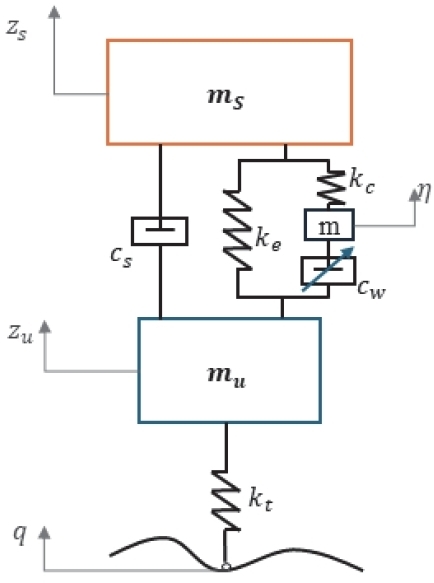
Quarter-truck with air suspension system configuration
The damper force and tire force are modeled as:
| (2) |
where cs is the damping coefficient, kt is the tire stiffness, and q is the road displacement input.
The air spring is modeled as a primary chamber connected to an auxiliary reservoir (accumulator) via an orifice. The following fundamental assumptions are made:
- • The air is treated as an ideal gas.
- • The process is polytropic, PVn = constant.
- • Heat transfer effects are captured by the polytropic index varies with temperature and volumetric changes to capture thermal dynamics.
- • Flow through the connecting pipeline is turbulent.
The pressure in the primary chamber (Pc) and the reservoir (Pr) are derived from the polytropic relation and mass conservation:
| (3) |
where Pc0, Vc0, Pr0, Vr0 are initial pressures and volumes. Ap is effective piston area of the main chamber. A is effective cross-sectional area related to the pipeline flow. η is displacement of the “gas column” in the pipeline. nc, nr are polytropic indices for the chamber and reservoir.
The polytropic index is modeled as variable to account for thermal and dynamic effects:
| (4) |
where n0 is the baseline index, and αT, αv are coefficients for thermal and velocity-dependent corrections.
The mass flow rate through the connecting orifice is modeled for turbulent flow using a quadratic dependence on the pressure difference:
| (5) |
where Cd is the discharge coefficient and ρ is the air density.
This mass flow is linked to the dynamics of the gas in the pipeline. Applying Newton's second law to the gas column, its motion is described by:
| (6) |
where L is the length of the connecting pipeline; ξ is the pressure loss coefficient due to friction; η represents the gas-column displacement in the pipeline.
The total force exerted by the air spring on the masses is a combination of the static pressure force and the dynamic flow-dependent force. A widely accepted and physically consistent model is used:
| (7) |
where PcAp is the primary force from the pressure in the main chamber acting on the piston area. km, cm are mechanical stiffness and damping coefficients representing the elastomeric components of the spring. Ka(η) is the stiffness coefficient related to the gas dynamics in the accumulator, which may be a function of η.
Substituting all force components into the equations of motion yields the final nonlinear model used for simulation and control design:
| (8) |
2.2 Fuzzy-PID Controller Design
The proposed control strategy enhances a conventional PID controller by dynamically adjusting its gains using a fuzzy inference system. This hybrid architecture aims to overcome the limitations of fixed-gain controllers in handling nonlinearities and operating condition variations.
The control force u(t) generated by the PID controller is given by:
| (9) |
where is the error between the desired and actual sprung mass displacement. In the active suspension context, is typically zero, representing the equilibrium position.
The proportional, integral, and derivative gains (Kp, Ki, Kd) are dynamically adjusted online based on the error e(t) and its derivative , which serve as the inputs to the fuzzy inference system.
Fuzzification: The inputs e(t) and are mapped into fuzzy sets using linguistic variables. The membership functions for both inputs are defined over the universe of discourse [-1, 1] with seven linguistic labels: Negative Big (NB), Negative Medium (NM), Negative Small (NS), Zero (ZE), Positive Small (PS), Positive Medium (PM), Positive Big (PB). A Gaussian membership function is employed for smooth transitions.
Fuzzy Rule Base: The core of the fuzzy system is a set of 49 rule of the form: IF e is Ai AND is Bj, THEN ΔKp is Ck, ΔKi is Dl, ΔKd is Em. where Ai, Bj are the input fuzzy sets and Ck, Dl, Em are the output fuzzy sets for the gain adjustments.
The following control strategies are designed to enforce the following control strategy:
- • When the error is large, increase Kp and Kd to improve response speed and reduce to prevent integral windup.
- • When the error is small, reduce Ki to minimize overshoot and increase to eliminate steady-state error.
- • When the error is increasing ( > 0), increase Kd to provide additional damping.
Inference and Defuzzification: The Mamdani fuzzy inference method is used to evaluate the rules. The output fuzzy sets for the gain adjustments are then converted into crisp values ΔKp, ΔKi, ΔKd using the centroid defuzzification method. The final, adaptive PID gains are computed as:

Fuzzy rule base for gain adjustment
| (10) |
where Kp0 , Ki0 , Kd0 are the baseline PID gains, typically obtained from preliminary tuning or optimization for a nominal operating condition.
This Fuzzy-PID architecture enables the controller to autonomously modulate its aggression and damping characteristics in response to the real-time state of the system, thereby maintaining high performance across the wide range of disturbances and operating conditions experienced by a heavy-duty truck. Two calibrated versions of this controller, termed Fuzzy-PID1 and Fuzzy-PID2, are presented in this study. Both controllers share the identical structure, rule base, and inputs described above. The distinction lies in the calibration of the gain-adjustment aggressiveness. Fuzzy-PID1 is tuned for a comfort-oriented response, utilizing narrower membership functions and conservative scaling factors that result in smoother, more moderate gain adjustments. In contrast, Fuzzy-PID2 is a stability-oriented variant, employing wider membership functions and more aggressive scaling to enable larger, more responsive gain modifications. This dual presentation demonstrates the inherent flexibility of the proposed fuzzy-PID framework, which can be tuned to prioritize different performance objectives—a key advantage over fixed-gain controllers.
3. Simulation and analysis
This section presents a comprehensive evaluation of the proposed control strategies through numerical simulations. The performance of the Passive, PID, Fuzzy, and two Fuzzy-PID controllers is assessed under excitation from an ISO8608-2016 Class B road profile at a vehicle speed of 60 km/h. The analysis focuses on key performance metrics including ride comfort, road-holding capability, and suspension working space.
The vehicle was subjected to a random road excitation conforming to ISO8608-2016 Class B standards, representing a typical average-quality paved road. As shown in Figure 2, the road profile exhibits characteristic random irregularities with an amplitude range of ±0.04 m, providing a realistic test scenario for evaluating suspension performance under highway driving conditions.
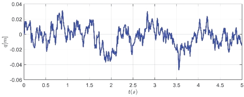
Road exogenous for simulation
Ride comfort, primarily determined by the vertical dynamics of the sprung mass, was evaluated through acceleration, velocity, and displacement metrics. Figure 3 illustrates the time-domain responses of the sprung mass acceleration (), while Table 2 provides the corresponding Root Mean Square (RMS) values for all comfort-related parameters.
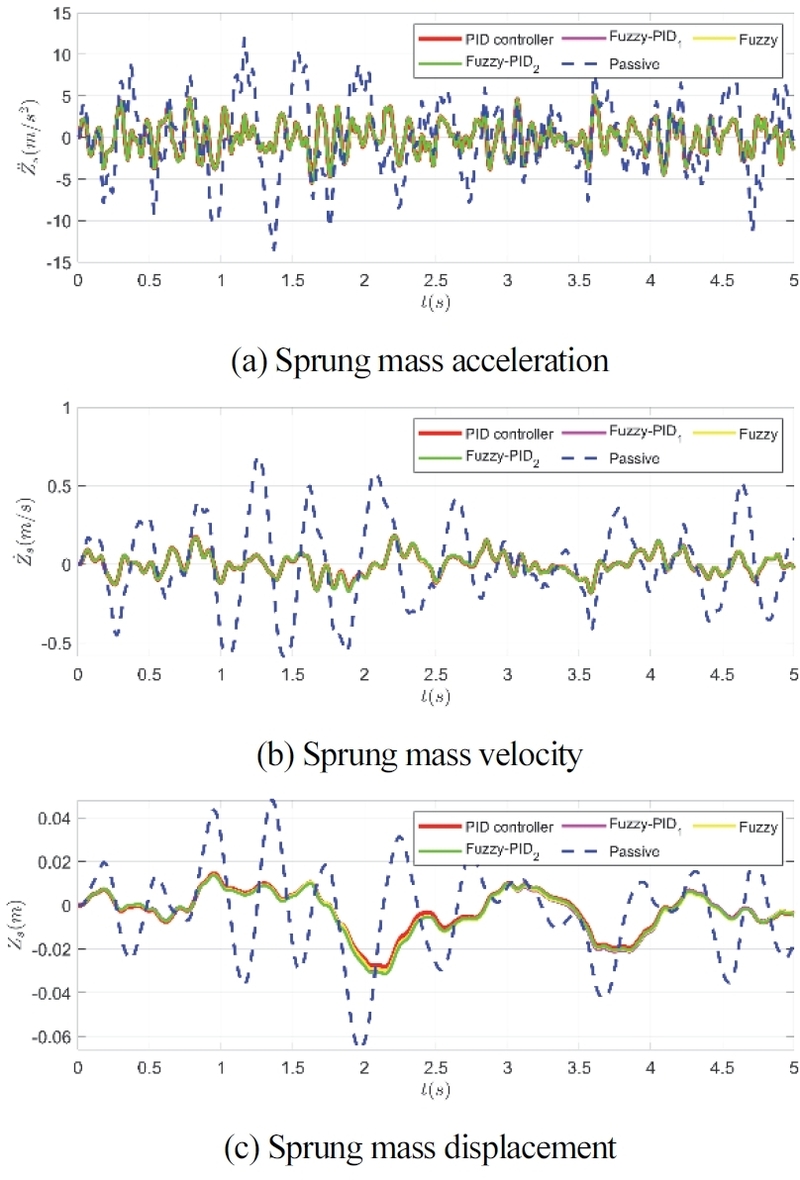
Sprung mass characteristics due to simulation
Ride comfort performance metrics (RMS values)
The results demonstrate considerable in ride comfort achieved by all active control strategies compared to the passive suspension. Specifically, the Fuzzy controller achieved the best performance in minimizing sprung mass acceleration with a reduction of 59.3 % compared to the passive system, closely followed by Fuzzy-PID1 (59.2 % reduction) and the conventional PID controller (58.7 % reduction). This significant attenuation of vertical acceleration directly translates to enhanced passenger comfort and reduced fatigue during extended driving periods.
Analysis of the sprung mass velocity reveals that the PID controller provided superior performance with a 76.1 % reduction relative to the passive system. The suspension travel, represented by the relative displacement between sprung and unsprung masses in Figure 3, shows that all active controllers effectively reduced the RMS displacement by approximately 50-55 %, with the Fuzzy controller achieving the best performance in this metric.
The suspension system's ability to maintain consistent tire-road contact is crucial for vehicle stability and safety. Figure 7 displays the dynamic tire load variations, while Table 3 summarizes the road-holding performance metrics.
Road-holding performance metrics
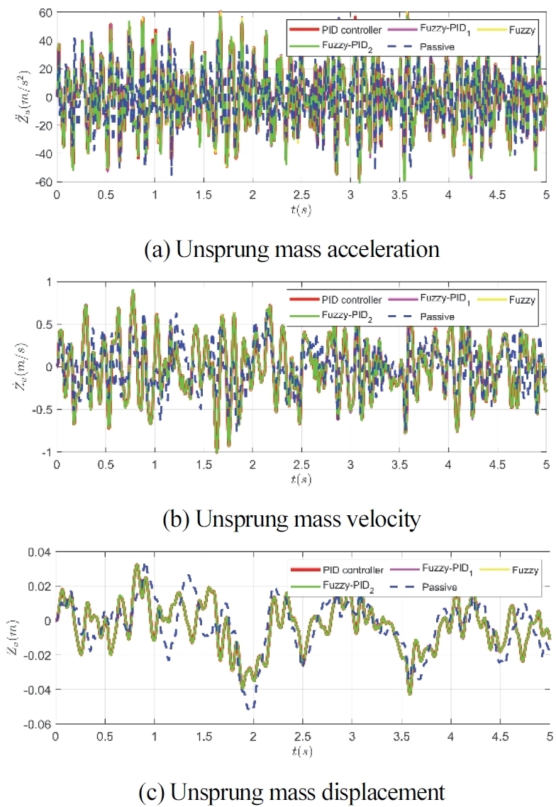
Unsprung mass characteristics due to simulation
The dynamic tire load (Fzd), a critical indicator of road-holding capability, shows remarkable improvement with the active control strategies. The Fuzzy-PID1 controller achieved the best performance with a 35.3 % reduction in dynamic load fluctuations compared to the passive system. This reduction indicates superior tire-road contact maintenance, which enhances traction and directional stability, particularly during cornering and braking maneuvers.
Notably, the unsprung mass acceleration increased with all active controllers, revealing a fundamental trade-off between ride comfort and road-holding. However, the Fuzzy-PID1 controller minimized this compromise, showing the lowest unsprung mass acceleration among the active control strategies while maintaining excellent comfort characteristics.
The suspension working space and energy consumption were evaluated through the relative displacement and control force requirements. Figure 5 illustrates the suspension deflection (zs - zu), while the control force metrics are presented in Table 4.
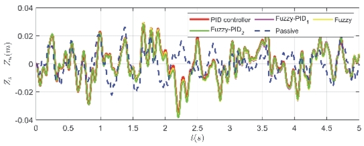
Suspension travel
Suspension system performance metrics
The results indicate that all active controllers dramatically reduced the spring force requirements by over 95 % compared to the passive suspension. The Fuzzy-PID1 controller demonstrated the highest energy efficiency, requiring the lowest control force among all active strategies. This reduction in force requirement not only improves energy efficiency but also reduces stress on suspension components, potentially extending their service life.
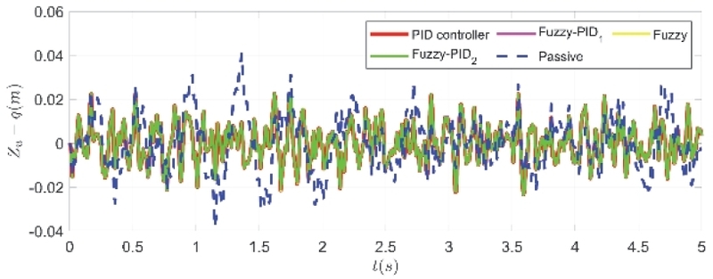
Tire-road displacement
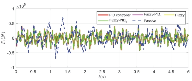
Dynamic load force on the road
4. Conclusions
This research has successfully developed and validated an adaptive Fuzzy-PID control strategy for heavy-duty truck air suspension systems, demonstrating its superior capability in resolving the fundamental conflict between ride comfort and road holding. Through comprehensive simulations on a high-fidelity nonlinear model under ISO8608 Class B road excitation at 60 km/h, the proposed controller achieved a substantial 59.2 % reduction in sprung mass acceleration for enhanced ride comfort, while simultaneously improving vehicle stability through a 35.3 % reduction in dynamic tire load fluctuations. The hybrid architecture effectively combines the precision of PID control with the adaptability of fuzzy logic, enabling real-time gain adjustment that outperforms both conventional PID and standalone fuzzy controllers.
The findings conclusively establish the Fuzzy-PID controller as an intelligent solution that provides a balanced optimization of conflicting performance objectives in nonlinear air suspension systems. By demonstrating significant improvements in both comfort and safety metrics while maintaining energy efficiency through reduced control force requirements, this research presents a robust control framework suitable for realworld automotive applications. Future work will focus on hardware-in-the-loop validation, expansion to full-vehicle models incorporating roll and pitch dynamics, and integration with broader vehicle control systems for comprehensive performance enhancement.
Nomenclature
| Ap : | effective piston area, m2 |
| Ar : | pipeline cross-sectional area, m2 |
| cs : | damping coefficient, Ns/m |
| Cd : | discharge coefficient |
| e(t) : | control error, m |
| F : | total air spring force, N |
| Fas : | air spring force, N |
| Fc : | control force, N |
| Fd : | damper force, N |
| Ft : | tire force, N |
| Fzd : | dynamic tire load, N |
| ft : | friction factor |
| Kp : | proportional gain |
| Ki : | integral gain |
| Kd : | derivative gain |
| kt : | tire stiffness, N/m |
| L : | pipeline length, m |
| ms : | sprung mass, kg |
| mu : | unsprung mass, kg |
| n : | polytropic index |
| P : | pressure, Pa |
| Pc : | chamber pressure, Pa |
| Pr : | reservoir pressure, Pa |
| q : | road displacement, m |
| Re : | reynolds number |
| t : | time, s |
| T : | temperature, K |
| u(t) : | controller output, N |
| zs : | sprung mass displacement, m |
| zu : | unsprung mass displacement, m |
| Acronyms | |
|---|---|
| ECAS : | electronically controlled air suspension |
| FLC : | fuzzy logic control |
| FIS : | fuzzy inference system |
| GA : | genetic algorithm |
| PID : | proportional-integral-derivative |
| RMS : | root mean square |
Acknowledgments
This research funded by the Electric Power University under project code DTKHCN.52/2025.
References
-
P. Pradhan and D. Singh, “Review on Air Suspension System,” Materials Today: Proceedings, Vol.81, No.2, pp.486-488, 2023.
[https://doi.org/10.1016/j.matpr.2021.03.640]

-
A. Shehata Gad and H. M. El-Zomor, “Semi-active Suspension Design for Truck Using Pneumatic Spring Joining MR Fluid Damper Based on Neural Networks Controller,” SAE International Journal of Vehicle Dynamics, Stability, and NVH, Vol.9, No.1, pp.10-09-01-0001, 2024.
[https://doi.org/10.4271/10-09-01-0001]
-
T. Vinod Kumar, M. Chandrasekaran, S. Padmanabhan, R. Saravanan and S. Arunkumar, “Material and Design Parameters Optimization to Enhance the Life of Anti-roll Bar of Commercial Truck,” Materials Today: Proceedings, Vol.37, No.1, pp.1359-1366, 2021.
[https://doi.org/10.1016/j.matpr.2020.06.561]
-
M. Y. Wu, H. Yin, X. B. Li, J. C. Lv, G. Q. Liang and Y. T. Wei, “A New Dynamic Stiffness Model with Hysteresis of Air Springs Based on Thermodynamics,” Journal of Sound and Vibration, Vol.521, Paper No.116693, 2022.
[https://doi.org/10.1016/j.jsv.2021.116693]
-
Z. Zhang and L. Zhao, “Analytical Calculation Method and Simulation of Deformation and Stress of Z-type Guide Arm for Interconnected Air Suspensions,” International Journal of Modeling, Simulation, and Scientific Computing, Vol.12, No.4, 2021.
[https://doi.org/10.1142/S1793962321500203]
-
H. Nazemian and M. Masih-Tehrani, “Development of an Optimized Game Controller for Energy Saving in a Novel Interconnected Air Suspension System,” Proceedings of the Institution of Mechanical Engineers, Part D: Journal of Automobile Engineering, Vol.234, No.13, pp.3068-3080, 2020.
[https://doi.org/10.1177/0954407020927147]
-
T. Lv, Y. Zhang, Y. Duan and J. Yang, “Kinematics and Compliance Analysis of Double Wishbone Air Suspension with Frictions and Joint Clearances,” Mechanism and Machine Theory, Vol.156, Paper No.104127, 2021.
[https://doi.org/10.1016/j.mechmachtheory.2020.104127]
-
Y. Zheng, W. B. Shangguan and S. Rakheja, “Modeling and Analysis of Time-domain Nonlinear Characteristics of Air Spring with an Auxiliary Chamber,” Mechanical Systems and Signal Processing, Vol.176, Paper No.109161, 2022.
[https://doi.org/10.1016/j.ymssp.2022.109161]
-
H. Zhu, J. Yang, Y. Zhang, X. Feng and Z. Ma, “Nonlinear Dynamic Model of Air Spring with a Damper for Vehicle Ride Comfort,” Nonlinear Dynamics, Vol.89, No.2, pp.1545-1568, 2017.
[https://doi.org/10.1007/s11071-017-3535-9]
-
Y. T. Zheng and Z. W. Wang, “Response Analysis of a Vehicle-cargo Coupling Model Considering Frequency-dependent Characteristics of Air Suspension,” Applied Sciences, Vol.15, No.16, pp.1-19, 2025.
[https://doi.org/10.3390/app15168945]
-
Z. Feng, M. Yu, S. A. Evangelou, I. M. Jaimoukha and D. Dini, “Feedforward PID Control of Full-car with Parallel Active Link Suspension for Improved Chassis Attitude Stabilization,” 2022 IEEE Conference on Control Technology and Applications (CCTA), pp.726-733, 2022.
[https://doi.org/10.1109/CCTA49430.2022.9966051]
-
H. Qi, Y. Chen, N. Zhang, B. Zhang, D. Wang and B. Tan, “Improvement of Both Handling Stability and Ride Comfort of a Vehicle via Coupled Hydraulically Interconnected Suspension and Electronic Controlled Air Spring,” Proceedings of the Institution of Mechanical Engineers, Part D: Journal of Automobile Engineering, Vol.234, No.2-3, pp.552-571, 2020.
[https://doi.org/10.1177/0954407019856538]
-
H. Kim and H. Lee, “Height and Leveling Control of Automotive Air Suspension System Using Sliding Mode Approach,” IEEE Transactions on Vehicular Technology, Vol.60, No.5, pp.2027-2041, 2011.
[https://doi.org/10.1109/TVT.2011.2138730]
-
X. Q. Sun, Y. F. Cai, C. C. Yuan, S. H. Wang and L. Chen, “Fuzzy Sliding Mode Control for the Vehicle Height and Leveling Adjustment System of an Electronic Air Suspension,” Chinese Journal of Mechanical Engineering (English Edition), Vol.31, No.1, Paper No.25, 2018.
[https://doi.org/10.1186/s10033-018-0223-8]
-
Y. Chen, Y. Hou, A. Peterson and M. Ahmadian, “Failure Mode and Effects Analysis of Dual Levelling Valve Airspring Suspensions on Truck Dynamics,” Vehicle System Dynamics, Vol.57, No.4, pp.617-635, 2019.
[https://doi.org/10.1080/00423114.2018.1480787]
-
P. Karimi Eskandary, A. Khajepour, A. Wong and M. Ansari, “Analysis and Optimization of Air Suspension System with Independent Height and Stiffness Tuning,” Int. J. Automotive Technology, Vol.17, No.5, pp.807-816, 2016.
[https://doi.org/10.1007/s12239-016-0079-9]
-
Z. Chen and J. Zhang, “Adaptive Neural Network Control of Heavy Vehicle Air Suspension with Uncertainties,” Journal of Vibration Engineering and Technologies, Vol.12, No.7, pp.8899-8915, 2024.
[https://doi.org/10.1007/s42417-024-01397-x]
-
H. Wang, P. K. Wong, J. Zhao and Z. X. Yang, “Observer-based Robust Gain-scheduled Control for Semi-active Air Suspension Systems Subject to Uncertainties and External Disturbance,” Mechanical Systems and Signal Processing, Vol.173, Paper No.109045, 2022.
[https://doi.org/10.1016/j.ymssp.2022.109045]
-
C. M. Ho and K. K. Ahn, “Observer Based Adaptive Neural Networks Fault-tolerant Control for Pneumatic Active Suspension with Vertical Constraint and Sensor Fault,” IEEE Transactions on Vehicular Technology, Vol.72, No.5, pp.5862-5876, 2023.
[https://doi.org/10.1109/TVT.2022.3230647]