Sensitivity Analysis of Steering Wheel Return-ability at Low Speed
Copyright ⓒ 2017 KSAE
Abstract
The steering wheel of a vehicle has a typical characteristic of automatically returning to its neutral state when the driver releases it. Steering returnability originated from the tire forces and kingpin moments. It is proportional to the reaction torque that is generated through the rack and column, which are dependent on suspension and steering geometry. It is also important to accurately predict and design it because steering returnability is related to steering performance. In this study, a detailed multibody dynamics model of a vehicle was designed by using ADAMS/Car and simulated for steering returnability. In addition, a tolerance analysis of the chassis system in terms of part dimension and properties has been performed in order to minimize the design parameters. The sensitivity of the selected design parameters was then analyzed via Design of Experiments(DOE). As a result, we were able to obtain the main parameters through a contribution analysis. It can be used to predict steering returnability and improve its performance, which is represented by the angle of restoration and laterality.
Keywords:
Rack friction, Sensitivity analysis, Steering return-ability, Steering torque, Kingpin moment, Tire force1. Introduction
The good handling performance of a vehicle may mean that a driver can operate more easily, rapidly and comfortably. Steering return-ability would be one of the important characteristics with respect to vehicle handling performance.1) Return-ability can be defined as characteristics of steering system which let a steering wheel return to the center position when driver’s hands are released after rotating a steering wheel.
Return-ability depends on kingpin moment which is related to kinematics caused by geometry of suspension and steering system and bush compliance effects. In addition to the kingpin moment, tire characteristics, friction and steering torque hysteresis are also significant return-ability factors.2)
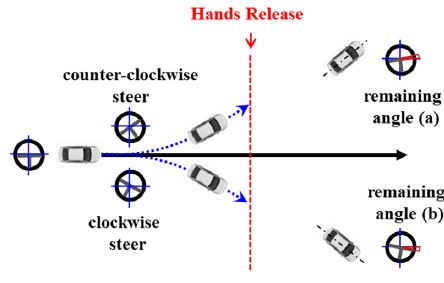
A number of studies on the steering wheel returnability have been advanced but there are still no investigations of laterality according to a restoring direction.3-7) The characteristics of return-ability is worked by a resisting torque on steering wheel so that Fig. 1 Steering return-ability test related to steering feel when performing a driving maneuver. Therefore aspects of steering feel, returnability according to a restoring direction must be considered from the beginning stage of vehicle development. In this study, electric power assistance is excluded to analyze the laterality for original returnability characteristics of the vehicle.
Generally, return-ability can be evaluated how well a steering wheel comes back to a neutral position. Particularly the remaining angle from a neutral position and restoring angular velocity are used criterion to evaluate its performance. And the vehicle with good performance for return-ability, generate less difference angle between left and right after restoring.
As shown in Fig. 1, in the steering return-ability test, a restoring angle and angular velocity are measured after a driver’s hands are released. And a laterality, the difference angle between a and b, is important measurement data too.
In this study, simulation studies are performed to analyze the cause of remaining angle and laterality in a steering return test. The influence of electric power assistance in the steering system is not considered in order to investigate the effects of kinematics only.8)
2. Restoring Mechanism of Steering Wheel
In a macpherson suspension system, front wheels are steered about an axis defined as kingpin axis which is determined by a ball joint of lower control arm and upper mounting of macpherson strut. For passenger cars, kingpin axis has generally offset from a tire center line on the ground because kingpin axis is inclined at 10 to 15 degrees relative to the vertical line when viewed from a front of vehicle. This inclination leads to moment around the kingpin axis.
2.1 Restoring Torque Generation Processes
The torque acting on a steering system is attributed to reacting forces and moments on the tire contact patch, for examples, normal force, lateral force, tractive force and aligning moment, rolling resistance moment and overturning moment according to the SAE convention. These forces generate kingpin moment and it contributes the restoring torque which is transferred to steering wheel through a tie-rod and a rack. However rolling resistance and overturning moment at most only have a sine angle component acting about the kingpin axis. They are second-order effects and so small that it can be neglected in analysis of steering system torques.9)
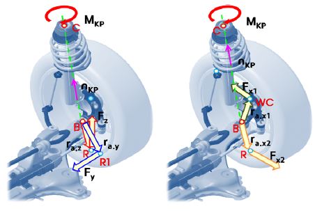
The moment of force around a specified axis can be calculated as follows: First, calculate the moment of force at a certain point on the axis. Then the moment projected onto the specified axis. In the same way, the kingpin moment of three direction forces(longitudinal, lateral and vertical force) acting on the tire contact patch are described in Equation (1) ~ (4).
A vector analysis is used to find the component of the moment along a specified axis that passes through the certain point. In Fig. 2, specified axis is the kingpin axis and a certain point is the point of ‘B’, the mounting point between lower control arm and knuckle, on the kingpin axis. First, calculate the moment of forces about point of ‘B’. And calculation of the moment about kingpin axis describe as Equation (1) ~ (4).
Kingpin moment of a vertical force
| (1) |
Kingpin moment of a lateral force
| (2) |
Kingpin moment of a longitudinal force
| (3) |
| (4) |
Aligning torque is corresponds to resistance to steer because it acts in the direction that restore the tire to center position. Component of aligning moment around kingpin axis can be calculated by Equation (5). Total moment around kingpin axis corresponds to the sum of moments around kingpin axis of each force and it can be expressed as Equation (6).
| (5) |
| (6) |
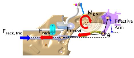
As previously described, forces and torques acting on the tire contact patch lead to moment around the kingpin axis and this moment may tend to transfer a force in the tie-rod along with the axial direction as shown in Fig. 3.
The tie-rod force can be calculated using a vector Equation given in Equation (7).10)
| (7) |
This force is also transmitted to the rack again, and it would be calculated by considering the friction loss as Equation (8).
| (8) |
The rack force is transmitted to steering column by a rack and pinion gear, and this force acts as restoring torque which tends to restore the steering wheel to center position. The influence of gear efficiency and column friction torque is considered to calculate the restoring torque as shown in Equation (9).
| (9) |
Equation (9) describes that the rack force may act as restoring torque entirely only when gear efficiency is 100 % and column friction becomes zero. However, these conditions are not possible in a real system so that a steering angle could not return perfectly after driver’s hands are released. Moreover there is a difference of restoring angle for left turn and right turn depending on vehicles, road surface, and other conditions. Thus these phenomena should be evaluated in order to improve steering performance.
2.2 Return-ability
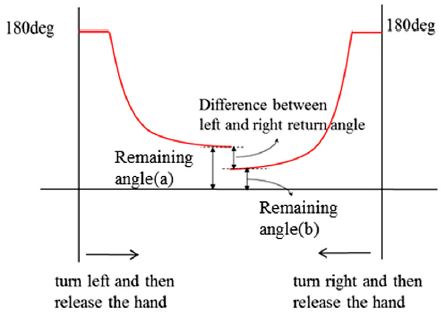
As explained previous Section 2.1, the operation mechanism of restoring torque is which forces and moments at a tire contact patch are contributed to kingpin moment and then it is transmitted on a tie-rod and a rack bar. As a result the torque to restore the steering wheel is finally implemented. During restoring maneuver by releasing driver’s hands, the remaining Fig. 4 Definition of the steering return-ability angle can be defined by the steering wheel angle that remains without being fully returned to the neutral position or the center of a steering wheel.
Fig. 4 shows a steering return-ability evaluation at a low speed. As shown in this Fig. 4(a) represents the remaining angle after counterclockwise rotation and Fig. 4(b) is denoted as the remaining angle after clockwise rotation. The difference of the remaining angle for counterclockwise and clockwise rotation corresponds to laterality of a return-ability which can be formulated as Fig. 4(a) subtracted from Fig. 4(b).
The remaining angle during a return test occurs apparently when the return force is smaller than the friction force and vice versus. On the other hand there are many factors contributed to a laterality in steering return-ability such as wheel alignment, vehicle load distribution, dimensional tolerances of body and chassis components, tire characteristics and disturbance of road surface gradient, etc. The magnitude and location of lateral force at the tire contact patch would be different for the left and right wheels by complicated interaction between these factors. As a result, kingpin moment about left wheels effect differently from right wheels and it leads to the difference of torque between each returning maneuver.
It is necessary to set the steering friction properly by considering the trade-off effects between friction feel and return-ability. Steering friction should be managed from the beginning stage of vehicle development so that quality problems due to steering torque difference between left and right turning can be addressed. In this study, sensitivity analysis is performed to determine main factors for return-ability and improving measures of its performance are proposed by using vehicle dynamics analysis.
3. Vehicle Dynamics Model
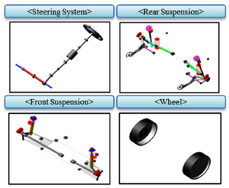
The sensitivity analysis for steering return-ability is conducted first by defining the candidate of influence factors. Then a vehicle model is utilized using ADAMS/Car for simulation of vehicle dynamics as shown in Fig. 5. Model parameter values were getting from one of the mid-size vehicle in Hyundai Motor Company. The vehicle model consist of macpherson strut front suspension system, four-link rear suspension system, the column type MDPS(Motor Driven Power Steering) for the steering system and anti-stabilizer bar. Tire model make use of a simplified form of Pacejka’s magic formula.
The effect of MDPS logic is excluded from this research, and the friction model of suspension and steering system is applied to investigate the effect on return-ability from the view point of a operation mechanism.
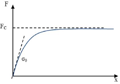
Particularly, the friction of a steering system is modeled using a hyperbolic tangent function. This friction model is simple, and can effectively realize the frictional characteristic in a real vehicle. This hyperbolic tangent function is similar to Dahl friction model which is represented by the shape of an exponential curve similar to a stress-strain function as shown in Fig. 6. Dahl friction model is one of useful friction models to represent a various attributes of a mechanical friction with only two variables such as the inclination and magnitude of a curve.11)
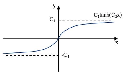
Compared to the Dahl friction, a hyperbolic tangent function is possible to specify more easily variables. For example, as shown in Fig. 7, the magnitude of the hyperbolic tangent function is determined by a constant C1, and the initial inclination of the curve is represented by a constant C2.
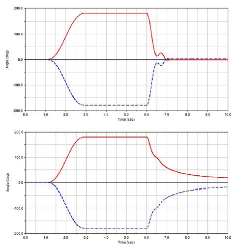
Based on this characteristic of a hyperbolic tangent function, the column friction force can be obtained by using the angular velocity of the column shaft. The rack friction force is dependent on axial velocity of the rack bar. In addition to above friction models, various friction terms are considered by implementing a viscous friction model and reflecting the difference between left and right frictions caused by the vertical clearance due to helix angle of the rack and pinion gear. Moreover, the effect of left and right friction difference on return-ability can be evaluated by applying an additional friction force on the left or right direction of rack movement.12) Steering friction on a MDPS motor and column system is imposed on the column as a lumped friction force, rack friction is similarly modeled. Suspension friction is also considered lumped friction acting on a suspension strut which is supposed to be equivalent to the friction on a strut mounting bearing and the ball joint of a lower control arm. The importance of friction models can be simply demonstrated using before and after comparison of friction models in terms of steering wheel angle during the return test as shown in Fig. 8.
It is apparent that the restoring rate is smaller and the restoring angle is larger using the vehicle model with friction than without friction. This result is identical to the behavior in the actual vehicle. Therefore the friction model should be included in a vehicle model in order to predict return-ability accurately.
In addition, tolerance analysis of a chassis system in terms of part dimension and properties is performed in order to improve simulation accuracy and achieve similar characteristics of actual vehicle.
4. Sensitivity Analysis
Sensitivity analysis of return-ability is performed based on design of experiment(DOE) using MINITAB, commercial statistical analysis software. DOE is one of popular statistical methods to find main parameters for a performance.
The procedure of sensitivity analysis is as follows: First, set objectives. Next, define responses of the experiment. And selecting design parameters that is affecting on the responses. Then select experimental design and execute the design. Finally, analyze the results and extract the main effects of return-ability.
[Set objectives]
This research covers that the sensitivity analysis of design parameters is focused on the restoring angle and laterality during low-speed restoration.
[Defining responses of experiments]
When the purpose of the experiment is determined, the responses of experiment as a characteristic value should be defined. In this paper, the remaining angle after counter clockwise steer, the remaining angle after clockwise steer, and the difference between both remaining angles are chosen for the return-ability test.
[Selecting design parameters and levels]
In the sensitivity analysis by DOE, to achieve the objective of experiment, all of relating factors should be selected as the design parameters. However, experiment with too many factors has low-quality on results. Therefore the minimum number of design parameters should be chosen by considering limited execution time and a cost.
In this paper, hard-points of suspension and steering system, chassis components related with compliance effect and tire characteristics are considered as design parameters. Particularly symmetrical parameters such as hard-points of suspension and steering system are defined independently by separating the left and right sides, and hard-points are subdivided into 3 components about the reference coordinate such as x, y and z. Based on all design parameters mentioned above, the number of design parameters is almost 134 so that it is too many to perform sensitivity analysis. Therefore, first of all, sensitivity analyses were performed using a onefactor-at-a-time approach to minimize design parameters. Then 25 design parameters are chosen as important factors by analyzing return-ability shown in Table 1.
When the difference between restoring angle after counter clockwise steer and clockwise steer is greater than 1°, these factors are selected the design parameters. Then selected design parameters are defined in two levels of the upper and lower limits of the tolerance.
[Select an experimental design and execute the design]
In general, two-level full factorial design with 25 design parameters requires 225 times of experiment that is 33,554,432 cases. This may not be possible practically; therefore experiments are established for the combination of design parameters considering randomness using Minitab.
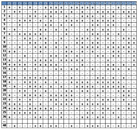
Plackett-Burman design which is one of fractional factorial design and is a convenient way if the number of experiments should be reduced, although the number of design parameters are too many. It is a concept to reduce the number of times of experiments by excluding interaction terms. In this study, using Plackett-Burman design, 48 different combinations of 25 factors generated as shown in Fig. 9. And simulations of steering return-ability were carried out on 48 cases using Adams/Car. Finally we analyzed sensitivity with the results and extract the main effects of return-ability.
5. Result and Discussion
5.1 Sensitivity Analysis of Laterality
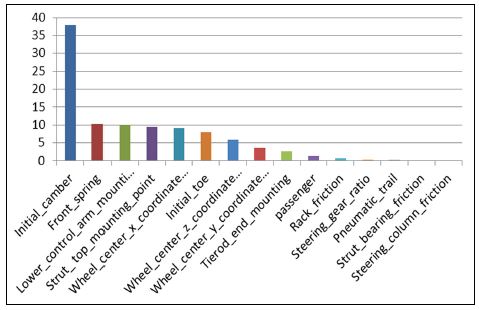
The results of sensitivity analysis according the DOE procedure described in Section 4 are used to evaluate return-ability. Regarding the difference between left and right restoring, main factors can be listed according to their influence rated from highest to lowest as Fig. 10: Initial camber, front spring, lower control arm joint, upper mounting of the strut, wheel center and initial toe.
From these results initial camber would be a key factor for return-ability. In addition, caster trail is important factor too. Caster trail is the distance from the intersection of the steering axis centerline with the ground, to the center of the tire contact patch. The lower control arm joint, the upper mounting of the strut and x coordinate of the wheel center are the factors that determine the caster trail. Initial toe is utilized as a factor to determine the restoring moment and contributes to slip angle, thus it affected on the laterality of restoring moment.
Initial camber(38 %), caster trail(28.6 %), front spring(10.3 %) and initial toe(8 %) have contributed to the change of laterality totally to about 85 % for the low speed test. Initial camber, toe and the front spring tend to induce the difference of restoring moment by different lateral forces, and caster induces a difference of restoring moment by different vertical forces at each wheel.
The lateral force generated in a tire contact patch can be simplified by a lateral force due to tire slip angle and camber angle, as following Equation (10).
| (10) |
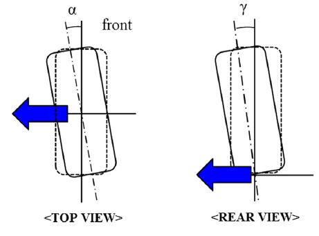
Here Cα is a cornering stiffness of tire due to slip angle and Cγ means a cornering stiffness of tire due to camber angle, α is slip angle and γ is camber angle positive slip angle and camber angle are defined as shown in Fig. 11.
According to the given Equation (10), the lateral force is proportional to slip angle and camber angle. The moment of each component due to the lateral force are given in Equations (11) and Equations (12).13)
Rotation moment due to the slip angle
| (11) |
Rotation moment due to the camber angle
| (12) |
In order to analyze the effect of the rotational moment caused by slip angle and camber angle on return-ability, simulation studies are performed by setting toe and camber angle asymmetrically.
In this study the tolerance specifications of the toe angle is ± 0.1°. If the maximum difference of toe angle between the left and right wheels up to 0.2° occurs, the difference between left and right remaining angle is about 2° ~ 3°.
Camber angle varies within the range ± 0.5°, and the camber angle difference between the left and right wheels also limits the range ± 0.5° which corresponds to cross-camber. Therefore, the worst case of the camber tolerance is considered by setting the camber angle difference between left and right wheels 0.5°, and the restoration analysis shows that the difference between left and right turn is about 6°~7°.
From the view point of return-ability, a smaller toe angle tends to reduce the remaining angle while a larger camber angle improves return-ability by generating larger lateral forces.
The caster angle is the angle between the vertical axis passing through a wheel center and kingpin axis from the side view of a vehicle. Caster trail is also defined as the distance from the point contacting the vertical axis on the ground at a wheel center and the point intersecting kingpin axis on the ground. Because of these suspension geometry, a normal force acting on the tire contact patch generates a restoring moment when turning a steering wheel, and the magnitude of restoring moment can be expressed by the following Equation (13).14)
| (13) |
Here the component of the normal force due to the kingpin angle is Fzrsinλ, and its restoring moment can be calculated by the product of the moment arm, dsinδ. In addition, the component of the normal force due to the caster is Fzrsinν and restoring moment corresponds to the product of the moment arm, dcosδ.
In order to investigate the effect of caster angle on return-ability, the point B of ball joint of the lower control arm is moved to 1mm forward and the point C of the upper mounting of the strut is adjusted to 1mm backward. This geometry modification increases caster angle, and is only implemented at one wheel, left or right wheel at a time for return-ability analysis. The return-ability analysis for asymmetric caster angles shows that the difference of remaining angles for each case is about 5° ~ 6° and steering toward the side of larger caster is returned better than steering toward the opposite side.
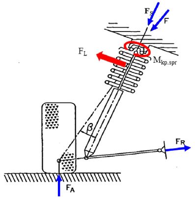
The forces acting on macpherson front suspension system is shown in Fig. 12 and consists of a normal force at the contact patch, and reaction forces at lower control arm, and a upper mounting of the strut.15)
When the resultant force of the normal force acting on a tire and the reaction force of a lower control arm do not coincide with the reaction force of a spring, the lateral force perpendicular to the direction of the spring reaction force is generated. This lateral force acts on the strut portion and generates a moment. The lateral force of the spring is influenced by the angle between kingpin axis and the strut axis. In addition, this lateral force of the spring is also affected by the spring load which is applied on the spring.
In this study, changing the spring rate is chosen as a factor of the spring and its effect due to the left and right difference on return-ability is investigated.
When the characteristics of left and right springs have different settings, it is confirmed that the returned angle varies by the difference between the left and right lateral forces. Considering the worst case of spring tolerance by setting the left and right spring rates with maximum and minimum tolerance respectively, the result of the return-ability analysis shows that the difference of remaining angles between left and right turns is about 3 degree. Moreover, steering toward the side of larger spring rate tends to return better than steering toward the opposite side.
5.2 Sensitivity analysis of restoring the steering wheel
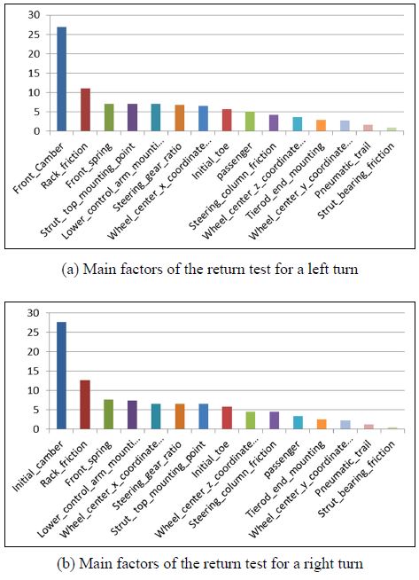
The results of sensitivity analysis related to the angle of the restoration can be found in a same manner. Main factors can be listed according to their influence rated from highest to lowest as Fig. 13; Initial camber, rack friction, front spring, the upper mounting of the strut, lower control arm joint, steering gear ratio and wheel center.
Friction is not greatly changed along with steering direction. Therefore, the influence of friction force on the laterality in return-ability is negligible but the effect on the remaining angle is very large.
Initial camber, caster trail that is determined from three points and front spring constant were also important with respect to remaining angle. This might be attributed to the difference of restoring moments at the left and right wheels corresponding inner/outer wheels or vice versa.
In other words, if the change of factors at the left side is the same as that at the right side the remaining angle would be small enough to neglect their contribution because their influence of the three factors, initial camber, caster trail, and front spring, will be canceled due to symmetricity.16)
Friction of the steering system is one of the important design parameters affecting the agility and on-center handling.17) In addition, the influence of friction is greater even in the return-ability. As a result of the preceding, in remaining angle, it can be seen that friction of the rack proportion is about 12 percent of the whole. Since the external forces transmit to the driver through the suspension and steering of the vehicle, the friction force must be properly managed. The friction force of steering gear is managed by an equivalent force, including the yoke, the rack&pinion gear and the rack bushing as defined by the rack pulling force. Rack pulling force value of the simulation model is about 150N, and the nreturn-ability an alysisis performed according to the friction deviation. As a result, difference between remain angle by friction deviation occurs about 5 degrees. As the friction force becomes larger, the return-ability tends to be deteriorated.
Steering gear ratio is defined by the transmitted distance of a rack when a steering wheel is turned. The sensitivity analysis shows that steering gear ratio has a contribution to the remaining angle about 7 % of return-ability.
Since the steering gear ratio does not manage its tolerance, the deviation of steering gear ratio is chosen arbitrary for return-ability analysis. The return-ability analysis shows that the larger the steering gear ratio is set the better return-ability can be achieved. In conclusion, summarizing the results up to now can be expressed as Table 2.
6. Conclusion
In this study, the detailed multi-body dynamic model of a vehicle was utilized using ADAMS/Car. The sensitivity analysis of the steering return-ability that contains laterality and parameter study were performed by using a design of experiments at low vehicle speed with large steering inputs. The conclusions are summarized as follows:
1) In order to extract the factors that affect the steering return-ability, the procedure of sensitivity analysis, based on design of experiment to find main parameters, was suggested and used to analyze a sensitivity of steering return-ability that contains remaining angle and laterality.
2) The sensitivity analysis based on DOE shows that wheel alignment such as camber, caster and toe is one of the most important factors in terms of laterality of return forces(the difference between left and right return forces), and rack friction has a large influence on the remaining angle. This sensitivity analysis is useful to predict and improve steering return-ability.
Nomenclature
| M : | moment |
| F : | force |
| r : | position vector |
| n : | unit vector |
| B : | mounting point between lower control arm and knuckle |
| R : | center of vertical and backward longitudinal force |
| R1 : | center of lateral force |
| WC : | center of forward longitudinal force |
| i : | steering rack gear ratio |
| C : | cornering stiffness |
| α : | slip angle |
| γ : | camber angle |
| e : | unit vector |
| d : | kingpin offset at the ground |
| ξ : | trail |
| ν : | caster angle |
Subscripts
| KP : | kingpin axis |
| KP.x1 : | tractive force about kingpin axis |
| KP.x2 : | braking force about kingpin axis |
| KP.y : | lateral force about kingpin axis |
| KP.z : | vertical force about kingpin axis |
| KP.align : | self-aligning torque about kingpin axis |
| align : | self-aligning torque |
| ax1 : | displacement (B~WC) |
| ax2 : | displacement (B~R) |
| ay : | displacement (B~R1) |
| az : | displacement (B~R) |
| x1 : | longitudinal (forward) direction |
| x2 : | longitudinal (backward) direction |
| y : | lateral direction |
| z : | vertical direction |
| tierod : | tie-rod |
| T : | displacement (B~H) |
| RH : | right side |
| LH : | left side |
| rack : | rack bar |
| fric.rack : | rack friction |
| fric.column : | column friction |
| SW : | steering wheel |
| KP.s : | lateral force due to side-slip angle about kingpin axis |
| S : | side-slip |
| KP.c : | lateral force due to camber about kingpin axis |
| c : | caster |
| p : | pneumatic |
| C : | camber |
| zl : | vertical direction at a left wheel |
| zr : | vertical direction at a right wheel |
References
-
P. E. Pfeffer, Interaction of Vehicle and Steering System Regarding On-Centre Handling, Ph. D. Dissertation, University of Bath, Bath, (2006).
[https://doi.org/10.1080/00423110701416519]

-
R. Avachat, J. S. Mahajan, and K. Gopalakrishna, “Development of Methodology for Improvement in Steering Returnability”, SAE 2008-01-0494, (2008).
[https://doi.org/10.4271/2008-01-0494]

- R. P. Rajvardhan, S. R. Shankapal, and S. M. Vijaykumar, “Effect of Wheel Geometry Parameters on Vehicle Steering”, SAS TECH Journal, Vol.9(Issue 2), p11-18, (2010).
-
R. Ledesma, and S. Shih, “The Effect of Kingpin Inclination Angle and Wheel Offset on Medium-duty Truck Handling”, SAE 2001-01-2732, (2001).
[https://doi.org/10.4271/2001-01-2732]

-
Y. Cho, and U. Lee, “Simulation of Steering Kickback Using Component Load Method”, SAE 2004-01-1097, (2004).
[https://doi.org/10.4271/2004-01-1097]

-
Y. Yasui, W. Tanaka, Y. Muragishi, E. Ono, M. Momiyama, H. Katoh, H. Aizawa, and Y. Imoto, “Estimation of Lateral Grip Margin Based on Self-aligning Torque for Vehicle Dynamics Ehancement”, SAE 2004-01-1070, (2004).
[https://doi.org/10.4271/2004-01-1070]

-
D. Kim, T. Tak, M. Kuk, J. Park, S. Shin, S. Song, H. Chun, C. Kim, S. Cho, and N. Cho, “Evaluation and Experimental Validation of Steering Efforts Considering Tire Static Friction Torque and Suspension and Steering Systems Characteristics”, SAE 2007-01-3641, (2007).
[https://doi.org/10.4271/2007-01-3641]

-
M. Kurishige, S. Wada, T. Kifuku, N. Inoue, R. Nishiyama, and S. Otagaki, “A New EPS Control Strategy to Improve Steering Wheel Returnability”, SAE 2000-01-0815, (2000).
[https://doi.org/10.4271/2000-01-0815]

-
T. D. Gillespie, Fundamentals of Vehicle Dynamics, Society of Automotive Engineers, (1992).
[https://doi.org/10.4271/r-114]

-
M. J. Kim, S. H. Chang, B. R. Lee, Y. D. Park, and H. S. Cho, “Rack Force Estimation Method Using a Tire Mesh Model”, Transactions of KSAE, Vol.22(No.3), p130-135, (2014).
[https://doi.org/10.7467/ksae.2014.22.3.130]

- C. H. Lee, and S. S. Kim, “Effects of Steering and Suspension Friction on On-center Handling Characteristics”, KSAE Annual Conference Proceedings, p945-951, (2012).
- M. G. Han, S. J. Kim, J. Y. Lee, K. I. Kim, J. G. Song, J. S. Shim, and S. J. Kil, “A Study on Reduction of Rattle Noise in Rack and Pinion of Steering System”, KSAE Spring Conference Proceedings, p722-727, (2008).
-
Y. G. Cho, “Vehicle Steering Returnability with Maximum Steering Wheel Angle at Low Speeds”, Int. J. Automotive Technology, Vol.10(No.4), p431-439, (2009).
[https://doi.org/10.1007/s12239-009-0049-6]

- G. H. Jo, S. H. Kim, M. C. Shin, J. Song, and C. N. Chu, “Estimation of Steering Torque with Tire Self-aligning Moment and Steering System Modeling”, KSAE Spring Conference Proceedings, p895-901, (2013).
- H. H. Kwon, and S. J. Choi, “A Study on the Delopment of the Side Load Coil Spring”, Journal of the KSMTE, Vol.7(No.5), p98-105, (1998).
- W. Matschinsky, Road Vehicle Suspensions, Professional Engineering Publishing Limited, London, (2000).
- I. L. Park, B. R. Lee, and J. H. Oh, “Improvement of Returnability in the Electric Power Steering Vehicle”, KSAE Fall Conference Proceedings, p604-609, (2007).
