PLL Technique of Regenerative Braking System Capable of Responding to Immediate Input Change
Copyright Ⓒ 2024 KSAE / 223-07
This is an Open-Access article distributed under the terms of the Creative Commons Attribution Non-Commercial License(http://creativecommons.org/licenses/by-nc/3.0) which permits unrestricted non-commercial use, distribution, and reproduction in any medium provided the original work is properly cited.
Abstract
The regenerative braking system of electric vehicles is one of the most important technologies in improving the fuel efficiency of electric vehicles. In this paper, the existing regenerative braking technology used in electric vehicles is briefly explained and the role of PLL in regenerative braking technology is explained. PSIM simulation verifies the PLL system and improves performance through tuning. This paper also identifies problems with the existing technology and subsequently suggests solutions to overcome such problems for eventual implementation. Finally, the specified problem is implemented to check whether the proposed system works well.
Keywords:
EV regeneration, Power factor, PLL, Inverter, Rectifier, Phase jump키워드:
전기차 회생제동, 역률, 위상동기회로, 인버터, 정류기, 위상 점프1. Introduction
A three-phase induction also known as an AC Induction(ACI) motor and PMSM(Permanent Magnet Synchronous Motor) are widely used in many industrial applications.1) Since electric vehicles receive energy through a three-phase motor, a regenerative braking system for energy recovery is important. Regenerative braking plays an important role in maximizing the energy efficiency of electric vehicles and increasing their driving range. This paper deals with the operating principle and importance of the regenerative braking system of an electric vehicle. First, the operating principle of the regenerative braking system and how to increase the energy efficiency of electric vehicles will be explained. Next, the existing PLL technique, which is a detection method according to the rapid change of the voltage generated by the motor in the regenerative braking system, is explained, and the performance is improved through PSIM simulation and tuning. The improved performance is confirmed by stabilization time or robustness to input distortion. In addition, the performance improvement of the method used in combination with the existing methods was experimentally verified in an extreme situation where the input changes rapidly.
2. Basic Theory of Ev Regeneration
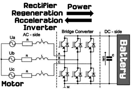
PFC(Power Factor Correction) in a general power system is to reduce harmonics of input/output voltage and current, whereas in automobiles, the direction of inverter power is controlled by controlling PFC. Electric vehicles basically charge(Regeneration) and discharge(Acceleration) according to the direction of power. When power comes out of the battery, it is acceleration, and when power goes into the battery, it is regeneration as Fig. 1.
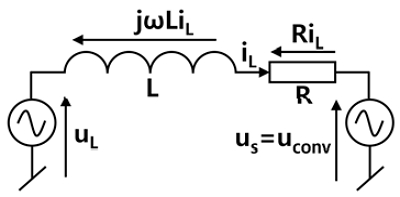
With Fig. 1, we can make an equivalent circuit and express it in regeneration mode as Fig. 2.
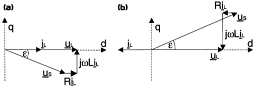
In order to implement a control algorithm for controlling output power or charging power appropriately in inverter operation or rectification operation as Fig. 3, it is necessary to convert voltage current parameters from a 3-axis fixed coordinate system to a 2-axis rotating coordinate system.
3. Basic Theory of Cordinate Translation
The voltages Ua, Ub, and Uc generated by the motor can be converted as shown in Equation 1 and 2 in a two-axis rotation coordinate system for convenience of calculation, and in the converted coordinate system, AC voltage can be used as DCs. And it can be inverse translated as equation 3 and 4.
| (1) |
| (2) |
| (3) |
| (4) |
The equation (1) and (3) has park, clarke, inverse park and inverse clarke transformation respectively.2) This process can be seen as the beginning of the most basic and important PLL system of power control.
4. Basic Theory of Power Factor Control (Regeneration)
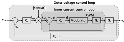
PFC basically has outer voltage control loop and inner current control loop as shown in Fig. 4, and all parameters are controlled with the output value of PLL. And also PLL system basically aims to calculate the frequency and phase of the input.
PLL systems were first designed and used in the 1930s for synchronous reception of radio signals, and have since been applied to a wide range of applications to estimate basic parameters of power(phase, frequency, amplitude, grid fault and voltage sag detection) in the field of power electronics.3-5)
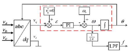
There are many types of PLL systems, such as SRF-PLL, SOGI PLL, DPLL, HT-PLL, SDFT-PLL, EPLL, OSG-PLL, etc., but this paper will cover SOGI PLL which is the most general and famous and Fig. 5 shows basic block diagram of 3phase PLL.6)
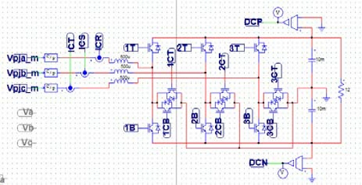
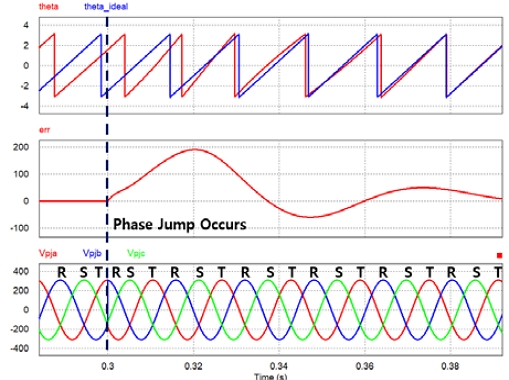
Fig. 6 shows the PFC simulation, and Fig. 7 shows how well the SOGI PLL implemented in the PFC system works.
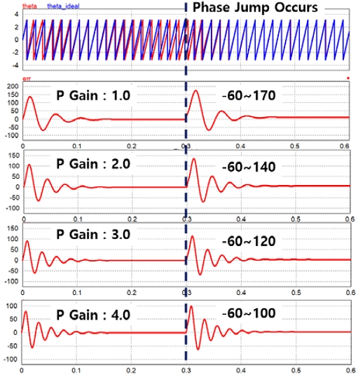
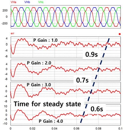
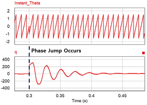
One of the important performance indicators of a PLL system is how quickly it can be stabilized when a phase jump occurs, and the other is how accurately it calculates θ when distortion occurs in the input. In order to improve this performance, PI(Proportional Integral) controller tuning in Fig. 6 is required, and Fig. 8 shows the change in stabilization time according to the change in P gain. And input voltage might have harmonic pollution(distortion), so Ii is necessary to verify how robust it is to input distortion.
In this paper, PFC is mentioned previously and there are equations showing the relation between THD(Total Harmonic Distortion) and Power Factor.7)
If the THD is high, the Power Factor gets lower showing equation (6). Fig. 9 shows the change in time until stabilization by changing the P gain when the 3rd, 5th, and 7th harmonics are included in the input calculated with equation (5).
| (5) |
| (6) |
The actual system showed slightly different results from the simulation due to various surrounding variables, so the gain tuning was conducted by trial and error, so the paper does not mention the optimal value of gain.
5. Problem of Conventional System and Solution
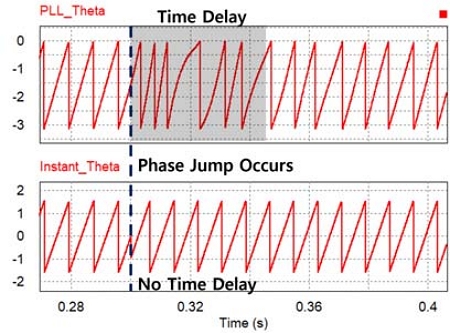
Existing PLLs, including SOGI PLLs, are based on PID control and APF(All pass filter), so there is a limit to the dynamic characteristics of the controller,8-10) so it is difficult to respond immediately to momentarily changing inputs. It means that conventional PLL is bound to have time delay as shown Fig. 12.
Since electric vehicles also need immediate control of voltage changes due to changes in wheel rotation caused by disturbance, how quickly the PLL responds will be an important technology for proper PFC implementation of electric vehicle systems. Therefore, in this paper, how quickly PWM(Pulse Width Modulation) is cut off when an abnormal input comes in is used as one of the performance indicators of PFC.
5.1 The solution of the problem
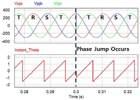
There are equation (7) that can calculate instantaneous α, β which is a clarke transformation and also instantaneous θ is calculated with equation (8). The instantaneous θ has no time delay when the phase jump occurs as shown Fig. 12. As shown Fig. 13, Instantaneous θ follows the input change immediately, whereas PLL θ takes time to follow the changed input. However instantaneous θ is not used as PLL because there are many problems in using it directly in the PLL and PFC system.
| (7) |
| (8) |
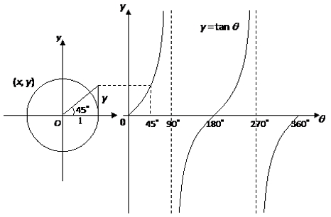
Among the various reasons not to use the instantaneous θ obtained using atan, the biggest reason is the limitation of the tan graph. Since it is impossible to distinguish between angle -90 ~ 90 and 90 ~ 270 only using tan result in Fig. 10, it is difficult to obtain the instantaneous θ for all angles without additional information. The reason why the PLL θ in Fig. 11 is calculated as atan results.
And the 2nd reason for not using instantaneous θ is because it is weak to noise.
However, it is possible to solve our problem by comparing the instantaneous θ obtained instantaneous θ and θ obtained through a PLL with relatively poor dynamic characteristics.
In other words, when the difference between instantaneous θ and θ calculated by the PLL exceeds a constant value, it can be determined that a sudden change in input has occurred.
Alternatively, as shown in Fig. 5 and 13, when q, which is controlled to 0,11) has a constant value instantaneously, it can be seen that the input has changed instantaneously as shown Fig. 14, that can also be a criterion for determining the change in input.
6. The Experiment Result
6.1 Experiment System
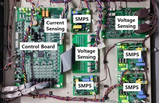
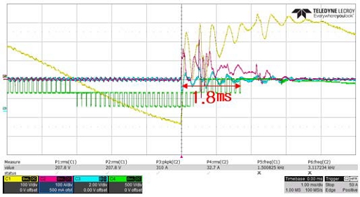
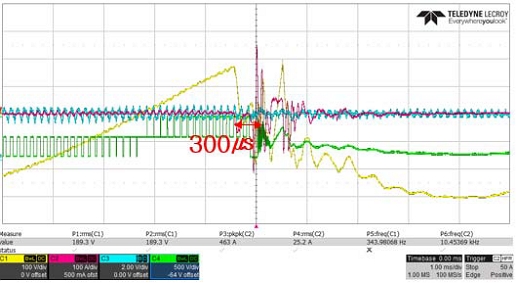
Fig. 14 and Table 1 show the picture and specification of experimental system designed for 30 kW power consumption respectively. The system has to cut off the PWM as quickly as possible when the Phase jump occurs and regenerate PWM with recalculated θ. Therefore, how quickly the PWM can be shut off is a factor that determines the performance of the system. Fig. 15 shows the existing system with slow cut off performance, and Fig. 16 shows the proposed system with improved performance.
It can be seen that the existing PFC system cuts off the PWM in 1.8 ms, whereas the proposed PFC system cuts off the PWM in 300 us, showing a performance improvement of 600 %.
7. Conclusion
In this paper, the role of PFC and PLL in the regenerative braking system of an electric vehicle was explained and their operation was verified through simulation. Performance improvement was confirmed through simulation tuning and calculating/comparing instantaneous θ. And the problems of the existing system were described, new solutions were presented, and verified through experiments. In the thesis, simply blocking PWM was used as a performance indicator, but in future research, it seems necessary to study how well it follows the change of input as an indicator.
Nomenclature
| Ua, Ub, Uc : | 3phase regenerated voltage from motor |
| Va, Vb, Vc : | 3phase input voltage of PLL system |
| Vd, Vq : | input voltage in 2 axis rotation coordinate |
| Vα, Vβ : | input voltage in 2 axis stationary coordinate |
| UL : | coordinate transformed input voltage |
| Us, Uconv : | coordinate transformed converter voltage |
| θ : | angle of vector |
| iL : | inductor current, A |
| R : | lekeage resistor, Ω |
| L : | lekeage or real inductance, H |
| Vn : | RMS voltage of the nth harmonic |
Acknowledgments
This study was carried out with the support of the KOREA Ministry of Land, National Transport Science and Technology Agency Promotion(RS-2023-00253588) and Joongbu University Research & Development Fund, in 2024.
References
-
D. G. Stănescu and P. M. Nicolae, “On the Efficiency of Asynchronous Motors Used in Urban Transportation Systems,” 15th International Power Electronics and Motion Control Conference (EPE/PEMC), pp.DS1c-7, 2012.
[https://doi.org/10.1109/EPEPEMC.2012.6397230]

- J. K. Kim, E. S. Cho, Y. K. Lee, J. W. Lee and J. H. Lee, “C++ Based Dynamic Model of AC Induction Motor in Discrete Time Domain”, IEEE Transportation Electrification Conference and Expo, Asia-Pacific (ITEC Asia-Pacific), pp.272-176, 2016.
- H. de Bellescize, “La réception synchrone,” Onde Electr., Vol.11, pp.230-240, 1932.
-
M. Ohrstrom and L. Soder, “Fast Protection of Strong Power Systems with Fault Current Limiters and PLL-aided Fault Detection,” IEEE Transactions on Power Delivery, Vol.26, No.3, pp.1538-1544, 2011.
[https://doi.org/10.1109/TPWRD.2011.2107530]

-
G. Chen, L. Zhang, R. Wang, L. Zhang and X. Cai, “A Novel SPLL and Voltage Sag Detection Based on LES Filters and Improved Instantaneous Symmetrical Components Method,” IEEE Transactions on Power Electronics, Vol.30, No.3, pp.1177-1188, 2015.
[https://doi.org/10.1109/TPEL.2014.2318051]

-
H. Du, Q. Sun, Q. Cheng, D. Ma and X. Wang, “An Adaptive Frequency Phase-Locked Loop Based on a Third Order Generalized Integral,” Energies, Vol.12, No.2, 2019.
[https://doi.org/10.3390/en12020309]

- M. H. Rashid, Power Electronics Handbook, pp.518-520, 2017.
-
T. -W. Chun, H. -H. Lee, H. -G. Kim and E. -C. Nho, “Synchronization Techniques for Single-Phase and Three-Phase Grid Connected Inverters Using PLL Algorithm,” The Transactions of the Korean Institute of Power Electronics, Vol.16, No.4, pp.309-316, 2011.
[https://doi.org/10.6113/TKPE.2011.16.4.309]

- F. M. Gardner, Phase Lock Techniques, New York: Wiley, 1979.
- T. Timbus, M. Liserres, R. Teodorescu and F. Blaabjerg, “Synchronization Methods for Three Phase Distributed Power Generation Systems, An Overview and Evaluation”, 36th Power Electronics Specialists Conference, pp.2474-2481, 2005.
- R. Y. Kim, S. Y. Choi and I. Y. Suh, “Instantaneous Control of Average Power for Grid Tie Inverter Using Phase D-Q Roatting Frame with All Pass Filter,” 30th Annual Conference of IEEE Industrial Electronics Society, Vol.1, pp.274-279, 2004.
