Urea-SCR System의 NH3 Slip 저감을 위한 NOx Sensor 기반 폐루프 제어기 개발에 관한 연구
Copyright Ⓒ 2021 KSAE / 183-01
This is an Open-Access article distributed under the terms of the Creative Commons Attribution Non-Commercial License(http://creativecommons.org/licenses/by-nc/3.0) which permits unrestricted non-commercial use, distribution, and reproduction in any medium provided the original work is properly cited.
Abstract
For non-road diesel engines of 56 kW or higher, the application of SCR is essential in order to comply with the NOx regulation of the current emission regulations. In order to maximize the NOx reduction efficiency of the SCR system, the NH3 adsorption characteristics of the SCR catalyst can be utilized. Since the NH3 adsorbed on the SCR catalyst has no direct measurement method, it is inevitable to rely on the NH3 adsorption estimation model, and there is a possibility that NH3 slip may occur due to model error. Therefore, this study proposed a closed loop control method in order to minimize NH3 slip by utilizing the NOx sensor signal at the SCR catalyst outlet. It was verified through the NRTC mode, the certification test mode for non-road diesel engines. As a result of the test, it was confirmed that the closed loop controller proposed in this study can reduce NH3 slip through detailed calibration.
Keywords:
Closed-loop controller, NH3 slip, SCR, DCU, Non-road diesel engine키워드:
폐루프 제어기, 암모니아 슬립, 선택적 환원촉매, 도징제어 장치, 비도로 디젤엔진1. 서 론
비도로용차량은 도로용 차량 대비 고부하 조건에서 운전되는 빈도가 높으며, 급격한 부하변동이 자주 나타나는 작동특성으로 인해 전통적으로 디젤엔진이 주요 동력원으로 사용되어 왔다. 특히 이러한 비도로용차량은 운행특성 및 작업환경 등으로 인해 전동화 차량의 보급이 쉽지 않은 상황이기 때문에 친환경⋅고효율 디젤엔진의 개발이 지속적으로 이루어져야 하는 분야이다.
비도로용 디젤엔진에 적용되는 배기규제로는 미국 연방정부의 Tier-4 final과 유럽연합의 Stage-Ⅴ등이 존재하며, 국내는 미국연방정부의 배기규제와 동일한 규제치를 도입시점에 차별을 두고 적용 중이다. 유럽연합의 Stage-Ⅴ는 2019년 도입된 배기규제 단계로 전 단계 규제인 Stage-Ⅳ와 비교 시 56∼130 kW 기준으로 PM 규제치가 0.025 g/kWh에서 0.015 g/kWh로 60 % 강화되었고 Stage-Ⅳ에 포함되지 않았던 PN 규제가 도입되어 1×10¹²#/kWh를 만족시켜야 하는 상황이다.1) 그간의 배기규제 동향을 살펴볼 때 차후 US-Tier 규제 또한 EU Stage-Ⅴ와 동등 또는 더 높은 수준의 규제치를 적용할 것으로 예상된다. 그로 인해 기존에 DPF 없이 규제치를 만족시키던 제작사들도 DPF를 필수적으로 장착해야 하는 상황이고, DPF 장착으로 인한 SCR의 열관리 대책 또한 필요한 상황이다.
현행 배기규제 만족을 위해서는 DOC, DPF, SCR, AOC 등 지금까지 양산화된 모든 배기저감기술이 적용되어야 하는 수준이며, 특히 56 kW급 이상의 비도로용 디젤엔진에서 NOx 규제치 만족을 위해서는 SCR의 적용은 필수적이라고 볼 수 있다. Urea-SCR system은 NH3 수용액을 환원제로 배기관 내에 공급하여 NOx를 N2와 H2O로 환원시키는 기술이다. Urea-SCR system은 NH3를 환원제로 사용하기 때문에 NOx와 반응하지 못하거나 SCR 촉매에 흡착되지 못한 NH3는 대기 중으로 방출되게 되는데, 이를 NH3 slip이라고 부르며,2) NH3는 강한 독성을 지니고 있는 물질이기 때문에 Urea-SCR 적용 엔진에 대해서는 NH3 배출량을 10 ppm 미만으로 규제하고 있다.3)
NH3 slip은 일반적으로 NH3/NOx의 비율이 1 이상인 상황에서 발생되며, Urea 분사를 통해 공급되는 NH3 외에도 SCR 촉매에 흡착되어 있는 NH3가 고온 조건에서 탈착되어 발생되는 경우도 존재한다. 따라서 높은 NOx 저감효율 달성과 NH3 slip 최소화라는 두 가지 목표를 동시에 달성하기 위해서는 DCU의 Urea 분사제어 전략이 매우 중요하다.4,5)
SCR 촉매에 흡착된 NH3는 직접적으로 측정할 수 있는 방법이 없기 때문에 NH3 흡착량 추정모델에 의존할 수밖에 없어 SCR 촉매온도에 따른 NH3 흡⋅탈착 특성 및 NH3 산화특성을 예측할 수 있는 모델의 개발 및 검증에 대한 연구가 진행된 바 있다.6-9) 선행연구에서는 공통적으로 모델오차에 따른 NH3 slip 발생 및 NOx 저감효율 저하가 발생할 수 있음을 언급하고 있으며, Herman 등은 이에 대한 대응책으로 NH3 센서를 활용한 폐루프 제어를 제시하였다.10-13) 이에 SCR 촉매 후단에 NH3 센서를 적용할 수 있다면 단순한 형태로의 폐루프 제어가 가능하지만 양산단계에서의 시스템 단가를 고려할 때 별도의 NH3 센서 없이 NH3 slip을 최소화할 수 있는 기술이 요구된다.
이에 본 연구에서는 SCR 촉매 후단의 NOx sensor signal을 활용하여 NH3 slip을 최소화할 수 있는 폐루프 제어방법을 제시하였으며, 비도로용 디젤엔진의 인증시험모드인 NRTC mode를 통해 검증하였다.
본 연구에서 제시된 폐루프 제어는 NOx 저감효율, SCR 촉매온도, SCR 촉매 전⋅후단 NOx 농도를 입력변수로 하여 NOx 저감효율이 100 %에 수렴하는 조건 하에서 SCR 후단 NOx sensor의 측정값이 증가할 때 이를 NH3 slip으로 판단하고 Urea 분사량 Gain curve를 통해 Urea 분사량을 감소시켜 NH3 slip을 저감시킬 수 있는 방식을 택하고 있다.
2. 실험장치 및 방법
Urea-SCR system의 폐루프 제어기 성능시험을 위해서 AVL社의 350 kW급 AC 엔진동력계와 Horiba社의 MEXA-9100DEGR 배출가스 분석기를 사용하였으며, NOx 분석은 화학발광법(Chemiluminescence Detector : CLD)을 채택하고 있다.
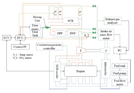
보조장비로 흡기유량계, 연료유량계, 냉각수 온도 조절장치, 인터쿨러 냉각장치가 사용되었으며, 배출가스 샘플포트는 SCR 후단에 설치하였다. Fig. 1은 전체 시험장치의 개략도를 나타낸다.
2.1 대상엔진 및 후처리장치
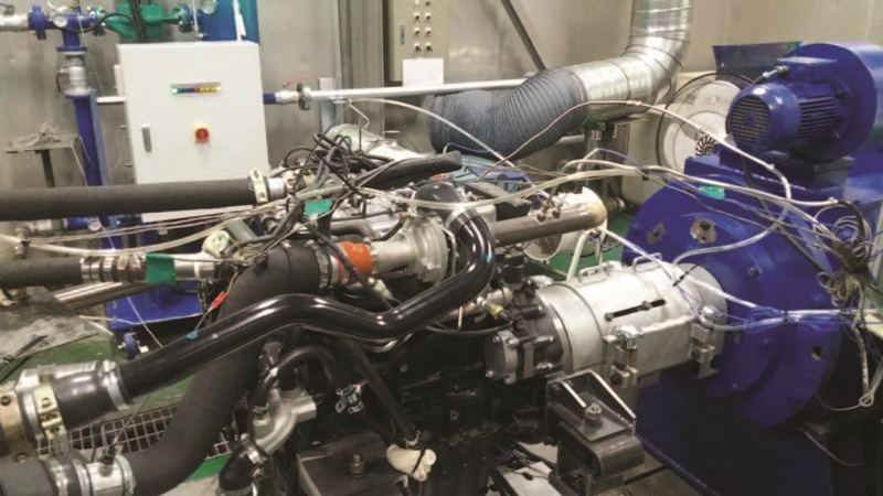
본 연구에 사용된 엔진은 배기량 3.8리터의 74 kW급 디젤엔진이며, 커먼레일 방식의 연료분사 시스템이 적용되어 있다. Table 1은 대상엔진의 주요 제원을, Fig. 2에 대상엔진의 외형을 나타내었다.
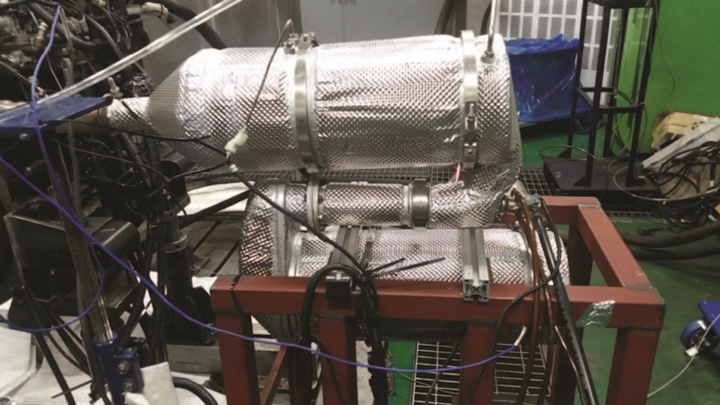
대상엔진에 적용된 배기후처리장치는 DOC + DPF + SCR + AOC의 구성이며, SCR 촉매 2개 중 후단촉매의 끝단 1 inch에 AOC가 Zone coating되어 있는 구조이다. Urea dosing system은 펌프 내장형 Urea tank와 배기관에 Urea를 분사할 수 있는 Dosing unit, Dosing system을 제어하는 DCU로 구성되어 있다. NOx sensor는 DOC 전단 및 SCR 후단에 각각 장착되어 있으며, SCR 전⋅후단에 각각 온도센서가 장착되어 있다. DCU는 엔진 ECU와 CAN통신이 가능하여 DOC, DPF 온도, 엔진회전속도, 연료분사량 및 배기유량 등은 엔진 ECU에서 CAN통신을 통해 DCU로 전송된다. Table 2에 후처리장치의 상세제원을, Fig. 3에 후처리장치의 외형을 나타내었다.
2.2 실험방법
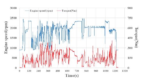
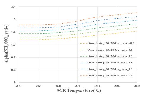
폐루프 제어기의 성능시험은 비도로용 디젤엔진의 인증시험모드인 NRTC cycle을 통해 진행하였으며, Fig. 4는 NRTC cycle의 엔진회전속도 및 토크를 나타낸다. 과도한 Urea 분사를 통해 NH3 slip을 유도하기 위해 기존의 NH3/NOx비의 30 %를 높여 설정하였으며, SCR 촉매온도 250 °C 기준 NH3 최대 흡착량의 90 %를 흡착시킨 상태로 시험을 진행하였다. Fig. 5는 SCR 온도 및 NO2/NOx ratio에 따른 과분사 조건의 NH3/NOx비율을 나타낸다.
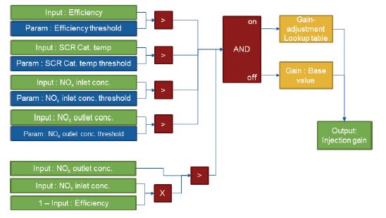
본 연구에서 제시된 폐루프 제어기는 Fig. 6과 같이 구성되어 있으며, 입력변수로 NOx 저감효율, SCR 촉매온도, SCR 촉매 전⋅후단 NOx 농도가 적용되며, 각 입력변수별로 Threshold를 설정할 수 있도록 구성되어 있다. 모든 입력변수별 Threshold값을 초과할 경우 폐루프 제어기의 Gain값에 따라 Urea 분사량이 조절되며, 하나의 입력변수라도 폐루프 제어기의 개입 조건을 만족시키지 못할 경우 기본 Gain값을 통해 Urea 분사량이 결정된다. 제어기는 기본 Gain값 또한 조정이 가능하도록 구성되어 있다.
3. 실험결과
3.1 기본성능평가
일차적으로 기본값으로 캘리브레이션이 완료된 DCU 데이터를 통해 NRTC cycle에서 대상엔진 및 후처리장치의 NOx 저감성능을 확인하였으며, 그 결과를 Fig. 7에 나타내었다. NRTC cycle 시험은 제작자동차 시험검사 및 절차에 관한 규정 별표 11의2에 따라 Cold 및 Hot 조건에서 수행되었다.16)
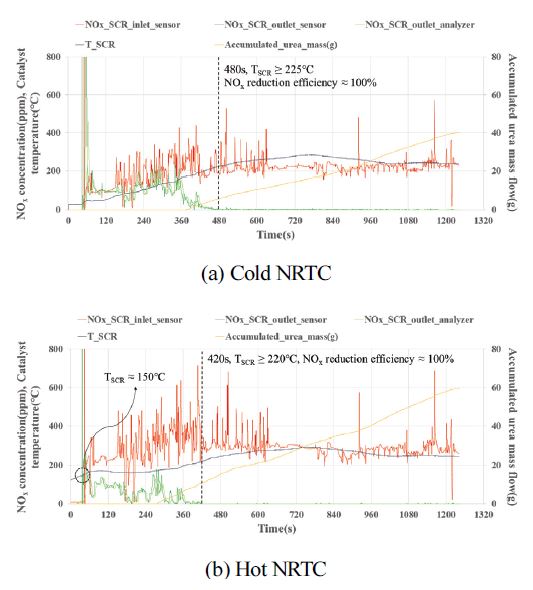
Results of NOx concentration, SCR catalyst temperature & accumulated urea mass flow with base calibration data on the NRTC cycle
Cold 조건의 경우 480초 지점에서 SCR 촉매의 온도가 225 °C에 도달하며, 이 지점부터는 NOx 저감효율이 100 %에 근접하는 것을 확인할 수 있다. Hot 조건에서는 약 420초 지점에서 SCR 촉매의 온도가 220 °C에 도달하며, 이 지점부터는 NOx 저감효율이 100 %에 근접하는 것을 확인할 수 있다. 또한 Cold 조건과 비교 시 Hot 조건은 모드 진입시점에서 이미 SCR 온도가 150 °C 정도 수준을 유지함으로써 Urea 분사시점 이전부터 SCR 촉매에 흡착되어 있는 NH3에 의해 NOx 저감반응이 일어난 것으로 판단된다. 배기관 온도가 낮은 조건에서 Urea 분사가 이루어질 경우 Deposit 발생의 위험이 존재하기 때문에 본 연구에서는 배기온도가 특정온도 이상에 도달하는 조건에서 Urea 분사가 되도록 설정하였다. Hot 조건의 경우 Cold 조건 대비 모드 진입 시의 SCR 촉매의 온도가 높은 상태로, Urea 분사가 시작되는 시점이 빠르기 때문에, Hot 조건에서 누적 Urea 분사량이 더 많은 것으로 판단된다.
3.2 폐루프 제어기 적용 시험결과
본 절에서는 제시된 폐루프 제어기의 적용 가능성 및 NH3 slip 제어성능을 확인하고자 2.2절에서 언급한 바와 같이 과도한 Urea 분사로 NH3 slip을 유도하기 위해 기존의 NH3/NOx비의 30 %를 높여 설정하였으며, SCR 촉매온도 250 °C 기준 NH3 최대 흡착량의 90 %를 흡착시킨 상태로 시험을 진행하였다.
Fig. 8은 NH3 slip이 발생하고 있는 조건에서 폐루프 제어기의 Gain값을 모두 1로 설정한 상태의 시험결과이다. 480∼1,000초 부근의 데이터를 살펴보면 SCR 촉매 후단에서 CLD분석기를 통해 측정된 NOx 농도는 0 ppm에 수렴하나, SCR 촉매 후단 NOx sensor에 의해 측정된 NOx 농도는 480초 부근에서 증가하기 시작해 660초 부근에서 최대 100 ppm까지 증가하였다가 서서히 감소함을 확인할 수 있다. 이는 NOx sensor의 cross-sensitivity 특성에 의한 것으로 NOx sensor와 CLD분석기와의 농도차가 발생되는 구간은 NH3 slip이 발생된 것으로 판단할 수 있다.14,15)
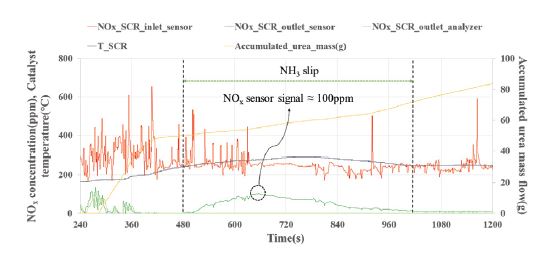
Results of NOx concentration, SCR catalyst temperature & accumulated urea mass flow with overdosing condition on the NRTC cycle
Fig. 9는 본 시험 조건에서의 NH3 최대흡착량, 현재흡착량, 타겟흡착량 및 Urea 분사량을 나타내고 있으며, 280초 부근에서 Urea 분사시점에 도달하여 타겟흡착량을 맞추기 위해 Urea 분사량이 급격히 증가하게 된다. 이후 430초 부근에서 현재흡착량이 타겟흡착량에 도달하게 되며, 450초 부근에서 최대흡착량에 도달하면서 Urea 분사량이 감소하게 된다. Fig. 8의 NH3 slip이 감지되는 지점과 현재흡착량이 최대흡착량을 넘어서는 지점은 거의 일치하는 것을 확인할 수 있으며, 현재흡착량이 타겟흡착량보다 낮아지는 940초 부근까지는 Urea 분사량을 감소시킴을 확인할 수 있다.
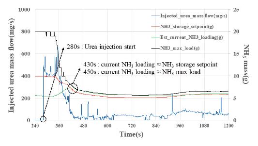
Injected urea mass flow, NH3 adsorption setpoint, current NH3 adsorption mass estimation value and maximum NH3 adsorption mass with overdosing condition on the NRTC cycle
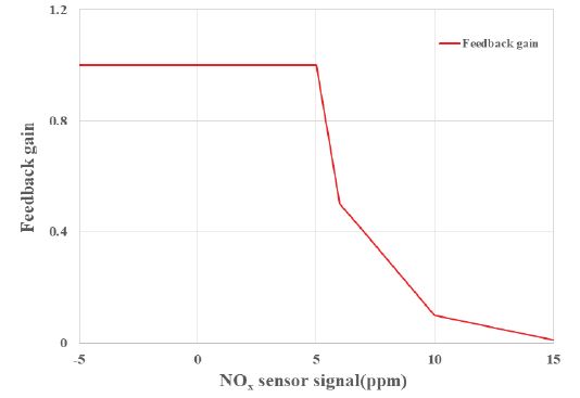
Fig. 10은 NH3 slip이 발생하고 있는 조건에서 폐루프 제어기의 Gain값을 Fig. 11의 값으로 설정하고 Filter time을 10초로 설정한 상태의 시험결과이다. SCR 촉매 후단에 장착된 NOx sensor에 의해 측정된 값을 Fig. 8의 Feedback gain이 1인 조건과 비교해보면 480∼1,000초 부근에서 NH3 slip이 발생되는 점은 유사하나, 780초 부근에서 최대 35 ppm 수준으로 NH3 slip이 억제되고 있음을 확인할 수 있다. 단, 이미 NH3의 최대 흡착량에 도달한 상태이기 때문에 NH3 slip이 감소하는 데에는 기존에 흡착된 NH3가 NOx와 반응하여 흡착량이 줄어들 때까지의 시간이 소요되는 것으로 판단된다.
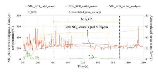
Results of NOx concentration, SCR catalyst temperature & accumulated urea mass flow with closed-loop controller(filter time : 10 sec) on the NRTC cycle
Fig. 12는 NRTC cycle상에서 폐루프 제어기가 작동하는 조건의 Feedback gain 및 Urea 분사량을 나타내고 있다. 480초 부근에서부터 Feedback gain이 1 이하로 조정되면서 Urea 분사량이 감소함을 확인할 수 있으며, 그 결과로 Fig. 8의 결과와 비교 시 후단 Urea 분사량 조정을 통해 NH3 slip이 억제되고 있음을 확인할 수 있다.
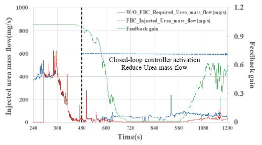
Injected urea mass flow with/without FBC controller and feedback gain on the NRTC cycle(filter time : 10 sec)
Fig. 13은 폐루프 제어기의 Filter time을 3초로 조정하였을 때의 시험결과이다. Fig. 9의 SCR 후단 NOx sensor에서 측정된 값과 비교 시 전반적으로 낮은 수치를 기록하고 있음을 확인할 수 있으며, 480∼1,000초 부근에서 NH3 slip이 발생되는 점은 유사하나, 780초 부근에서 최대 22 ppm 수준으로 NH3 slip에 대한 억제력이 강화된 것을 확인할 수 있다.
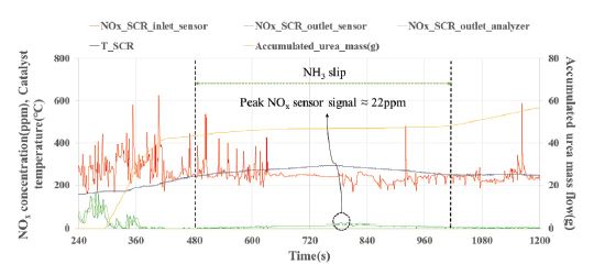
Results of NOx concentration, each catalyst temperature & accumulated urea mass flow with closed-loop controller(filter time : 3 sec) on the NRTC cycle
Fig. 14의 Feedback gain 및 Urea 분사량을 확인해 보면 Filter time 변경으로 인해 Gain값의 변동이 더 크게 나타나는 것을 확인할 수 있으며, 이에 따라 Urea 분사량 또한 변동폭이 커진 것을 확인할 수 있다. 폐루프 제어기의 Filter time을 짧게 설정할 경우 그만큼 NH3 slip 억제력은 강화될 수 있으나, 순간적으로 비정상적인 NOx sensor의 signal이 검출될 경우 Urea 분사량을 줄여 NOx 저감효율이 감소될 수 있는 가능성도 존재하기 때문에 이에 대한 다수의 시험데이터 획득 및 최적 Filter time 설정이 필요할 것으로 판단된다.
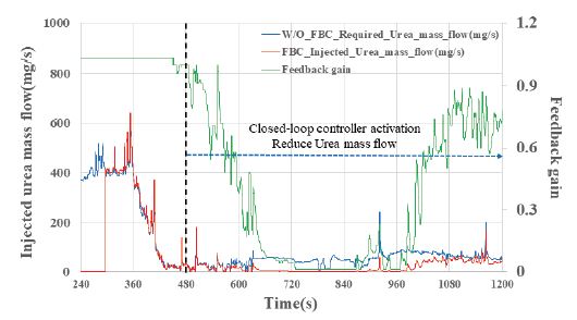
Injected urea mass flow with/without FBC controller and feedback gain on the NRTC cycle(filter time : 3 sec)
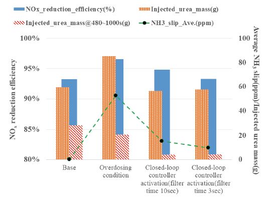
Fig. 15는 각 시험 조건별 NOx 저감효율, 사이클 운전 중 분사된 총 Urea 분사량, 480∼1,000초 사이의 Urea 분사량 및 NH3 slip의 평균값을 나타내었다. NOx 저감효율과 Urea 분사량은 기본적으로 비례관계를 나타내는 것을 확인할 수 있으며, 폐루프 제어기의 개입을 통해 Urea 분사량을 감소시킬 경우 NH3 slip이 감소함을 확인할 수 있다. 이에 폐루프 제어기의 Feedback gain 설정을 과하게 할 경우 NOx 저감효율이 감소할 수 있을 것으로 판단되어 이에 대한 다수의 시험데이터 획득 및 최적 Gain값 설정이 필요한 것으로 판단된다. 폐루프 제어기 개입 시 480∼1,000초 사이에 80 % 가량 Urea 분사량이 감소하였으며, 이를 통해 NH3 slip이 Filter time이 10초일 경우 71 %, Filter time이 3초일 경우 82 % 감소됨을 확인하였다. 본 결과를 토대로 판단할 때 폐루프 제어기의 반응속도에 따라 NH3 slip 억제능력이 달라질 수 있음을 확인할 수 있으며, 폐루프 제어기가 개입하는 조건은 기본적으로 SCR 촉매의 최대 NH3 흡착량을 초과하는 조건이며 SCR 촉매는 고온에서 최대 흡착량이 감소하는 특성을 가지기 때문에 SCR 촉매 온도에 따른 Filter time을 설정할 수 있도록 모델을 구성하는 것이 타당할 것으로 판단된다. 또한 현재 폐루프 제어기에서 Feedback gain은 후단 NOx sensor signal에 의해 결정되게 되어 있으나, SCR 촉매 온도와 후단 NOx sensor signal을 입력변수로 하여 3D MAP 형태의 Look-up table로 구성할 경우 최대 NOx 저감효율을 얻는 동시에 NH3 slip 억제능력을 극대화할 수 있을 것으로 판단된다.
4. 결 론
- 1) 본 연구에서는 비도로용 디젤엔진에 Urea-SCR system 적용 시 NH3 slip 저감을 위해 NOx sensor의 Cross-sensitivity 특성을 활용한 폐루프 제어방법을 제시하였으며, 이는 제어기의 개입 조건, SCR 후단 NOx sensor signal에 따른 Gain값 및 Filter time 설정을 통해 Urea 분사량을 조정하여 NH3 slip을 억제할 수 있다.
- 2) SCR 촉매에 흡착된 NH3의 질량이 최대흡착량에 도달한 경우 NH3 slip이 발생될 수 있으며, 이미 NH3 slip이 발생되는 상황에서 폐루프 제어기가 Urea 분사량을 조정하더라도 NH3 slip이 감소되는 시점까지 시간적인 여유가 필요하다.
- 3) 제시된 폐루프 제어기를 DCU에 적용하여 비도로용 디젤엔진의 인증시험모드인 NRTC cycle상에서 폐루프 제어기의 성능을 검증하였으며, 세부적인 파라미터 튜닝을 통해 NH3 slip을 억제할 수 있음을 확인하였다.
Nomenclature
| AOC : | ammonia oxidation catalyst |
| CAN : | controller area network |
| CLD : | chemiluminescence detector |
| DCU : | dosing control unit |
| DOC : | diesel oxidation catalyst |
| DPF : | diesel particulate filter |
| ECU : | engine control unit |
| NRTC : | non-road transient cycle |
| PM : | particulate matter |
| PN : | particulate number |
| SCR : | selective catalyst reduction |
Acknowledgments
본 연구는 산업통상자원부의 재원으로 산업기술혁신사업의 지원을 받아 수행된 연구임(10077690, Post Tier-4 대응 100마력급 비도로용 디젤엔진 질소산화물 저감용 우레아 공급 시스템 개발).
References
- D. S. Kim and T. J. Wang, “Diesel Engine Technologies for Next-generation Stage Ⅴ Emission Regulation,” Auto Journal, KSAE, Vol.39, No.2, pp.25-30, 2017.
- J. C. Kim, “Urea-Selective Catalyst Reduction System,” Auto Journal, KSAE, Vol.38, No.5, pp.37-41, 2016.
- S. H. Kang, Development of Nitrogen Oxide Prediction Model for Passenger Diesel Engine, Ph. D. Dissertation, Kookmin University, Seoul, 2016.
- S. J. Jeong, S. J. Lee, W. S. Kim and C. B. Lee, “Numerical Study on the Injector Shape and Location of Urea-SCR System of Heavy-duty Diesel Engine for Preventing NH3 Slip,” Transactions of KSAE, Vol.14, No.1, pp.68-78, 2006.
- S. J. Jeong, H. K. Lee, S. D. Oh, J. K. Park, Y. D. Kim, S. S. M. Shim and W. S. Kim, “A Study on NOx and NH3 Emission Characteristics of Urea SCR Dosing System According to Control Algorithms,” KSAE Annual Conference Proceedings, pp.707-714, 2009.
-
Y. Y. Ham and S. Y. Park, “A Study of NH3 Adsorption/Desorption Characteristics and Model Based Control in the Urea-SCR System,” Transactions of KSAE, Vol.24, No.3, pp.302-309, 2016.
[https://doi.org/10.7467/KSAE.2016.24.3.302]

-
A. Schuler, M. Votsmeier, P. Kiwic, J. Gieshoff, W. Hautpmann, A. Drochner and H. Vogel, “NH3-SCR on Fe Zeolite Cataysts - from Model Setup to NH3 Dosing,” Chemical Engineering Journal, Vo1.154, Issues 1-3, pp.333-340, 2009.
[https://doi.org/10.1016/j.cej.2009.02.037]

-
M. Colombo, G. Koltsakis, I. Nova and E. Tronconi, “Modelling the Ammonia Adsorption-desorption Process Over an Fe-zeolite Catalyst for SCR Automotive Applications,” Catalysis Today, Vol.188, No.1, pp.42-52, 2012.
[https://doi.org/10.1016/j.cattod.2011.09.002]

- T. Wang, S. Baek, M. Jung and G. Yeo, “A Study of NH3 Adsorption/Desorption Characteristics in the Monolithic NH3-SCR Reactor,” Transactions of KSAE, Vol.14, No.3, pp.125-132, 2006.
-
A. Herman, M. C. Wu, D. Cabush and M. Shost, “Model Based Control of SCR Dosing and OBD Strategies with Feedback from NH3 Sensors,” SAE 2009-01-0911, 2009.
[https://doi.org/10.4271/2009-01-0911]

-
M. Shost, J. Noetzel, M. C. Wu, T. Sugiarto, T. Bordewyk, G. Fulks and G. B. Fisher, “Monitoring, Feedback and Control of Urea SCR Dosing Systems for NOx Reduction : Utilizing an Embedded Model and Ammonia Sensing,” SAE 2008-01-1325, 2008.
[https://doi.org/10.4271/2008-01-1325]

-
F. Willems, R. Cloudt, E. Eijnden, M. Genderen, R. Verbeek, B. Jager, W. Boomsma and I. Heuvel, “Is Closed-Loop SCR Control Required to Meet Future Emission Targets?,” SAE 2007-01-1574, 2007.
[https://doi.org/10.4271/2007-01-1574]

- D. H. E. Seher, M. Reichelt and S. Wickert, “Control Strategy for NOx - Emission Reduction with SCR,” SAE 2003-01-3362, 2003.
- A. Bonfils, Experimental Closed-loop Control of SCR After-treatment Systems Using NOx Sensors Cross-sensitivite to NH3, Ph. D. Dissertation, Paris Institute of Technology, Paris, 2013.
- M. F. Hsieh, Control of Diesel Engine Urea Selective Catalytic Reduction System, Ph. D. Dissertation, Ohio State University, Columbus, 2010.
- 환경부, 제작자동차 시험검사 및 절차에 관한 규정, 별표 11의2 - 건설기계의 NRTC 및 NRSC 모드 측정방법, 2020.

